9
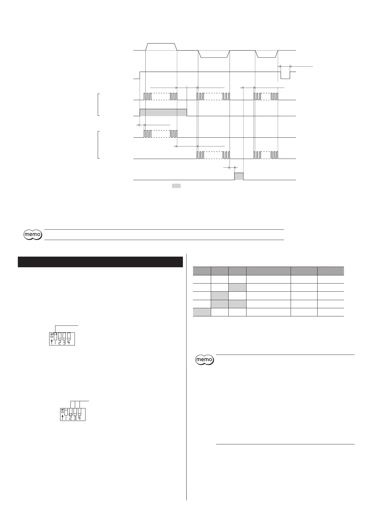
Timing chart
*3
*4
ON
OFF
ON
OFF
ON
OFF
ON
OFF
ON
OFF
ON
OFF
DIR input
CW input
CCW input
PLS input
AWO input
Motor operation
Power supply input
10 µs or more
0.5 s or more
10 µs or more
*2
2-pulse input mode
1-pulse input mode
10 µs or more
*1
*1 *1
CW
CCW
The section indicates that the photocoupler diode is emitting light.
CW
CCW CCW
5 s or more
300 µs or more
*1 10 µs or more for the switching time of the DIR input (for 1-pulse input mode) and the switching time of the CW input and CCW input (2-pulse input mode) represents
the response time of the driver. Set it to the time required for the motor to respond to the applicable pulse input.
*2 The specic duration varies depending on the load inertial moment, load torque, starting frequency, etc.
*3 Do not input pulse signals immediately after switching the AWO input to OFF, given that it will aect the motor’s starting characteristics.
*4 When cycling the power supply, turn o the power and turn on the power again after waiting for 5 second or more.
The maximum response frequency is 100 kHz at a pulse duty of 50%.
Setting
Pulse input mode
Either the 1-pulse input mode or 2-pulse input mode can be selected in
accordance with the controller used.
Sets a desired mode using the pulse input mode setting switch (SW-1).
The factory setting of the pulse-input mode depends on the destination
country.
Pulse input mode setting switch (SW-1)
ON: 2-pulse input mode
OFF: 1-pulse input mode
Step angle
Sets the motor step angle using the step angle setting switches (SW-2, SW-3,
SW-4). See the next table for the step angles that can be set.
Factory setting All OFF
Step angle setting switches
(SW-2, SW-3, SW-4)
When the base step angle is 1.8°/step
SW-2 SW-3 SW-4 Number of divisions Resolution Step angle
OFF OFF OFF 1 200 1.8°
OFF OFF ON 2 400 0.9°
OFF ON OFF 4 800 0.45°
OFF ON ON 8 1,600 0.225°
ON OFF OFF 16 3,200 0.1125°
The step angle is calculated by dividing the base step angle by the number of
divisions.
If the switches are set to any combination other than those listed in the table,
the number of divisions will become one and the motor will operate at the
base step angle.
y
Step angles are theoretical values.
y
The step angle set by the step angle setting switches becomes
eective when the CS input is OFF.
y
Do not change the CS input or the step angle setting switch while
operating. Doing so may cause loss of synchronism of the motor,
resulting in the motor standstill. Set the step angle setting switches
when the CS input is OFF and TIM output is ON.
y
For the high-resolution type, in comparison with the standard type
the resolution is twice and the step angle is one-half.
Example: When SW-2, SW-3, and SW-4 are all OFF
Resolution of the high-resolution type: 200 × 2 = 400
Step angle of the high-resolution type: 1.8°/2 = 0.9°
y
With the geared motor, the actual step angle is calculated by
dividing the step angle by the gear ratio.