10
Motor current
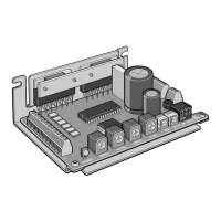
Set the motor current using the motor operating current setting switch (RUN)
and motor standstill current potentiometer (STOP).
Motor standstill current
potentiometer
STOP
Motor operating current
setting switch
When the load is light and there is a margin for motor torque, the motor’s
operating vibration and the temperature increase of the motor and driver
can be held down by lowering the motor’s operating current and standstill
current.
z
Operation current
The motor operating current setting switch (RUN) can be used to set the 16
operating current levels.
Set the operating current to less than the motor rated current.
Factory setting F
Dial setting
Operating current (A/phase) [Representative values]
CMD2109P CMD2112P CMD2120P
0 0.12 0.29 0.58
1 0.15 0.36 0.68
2 0.28 0.41 0.77
3 0.33 0.47 0.87
4 0.38 0.54 0.96
5 0.43 0.59 1.05
6 0.49 0.66 1.15
7 0.54 0.72 1.24
8 0.59 0.78 1.35
9 0.64 0.84 1.44
A 0.7 0.9 1.53
B 0.75 0.96 1.62
C 0.8 1.02 1.71
D 0.85 1.08 1.8
E 0.9 1.14 1.9
F 0.95 1.2 2
If the operating current is larger than the motor rated current, the
motor generates heat, causing a burnout or a skin burn(s).
The actual operating current may vary from the applicable value in
the table depending on the motor used.
z
Standstill current
Set the motor standstill current using the motor standstill current
potentiometer (STOP).
The motor standstill current is the motor operating current multiplied by
current cutback ratio.
Factory setting 40% of the operating current
y
A range of adjustment of the current at motor standstill is within
40% of motor operating current. When the current at motor
standstill is decreased too much, motor starting or maintenance
of the location may be hindered. Do not reduce it any more than is
necessary.
y
When operating the potentiometer, use a insulated precision
screwdriver.
y
When setting the current at motor standstill, be sure to do so after
setting the motor’s operating current and turning o the power
supply to the driver.
•
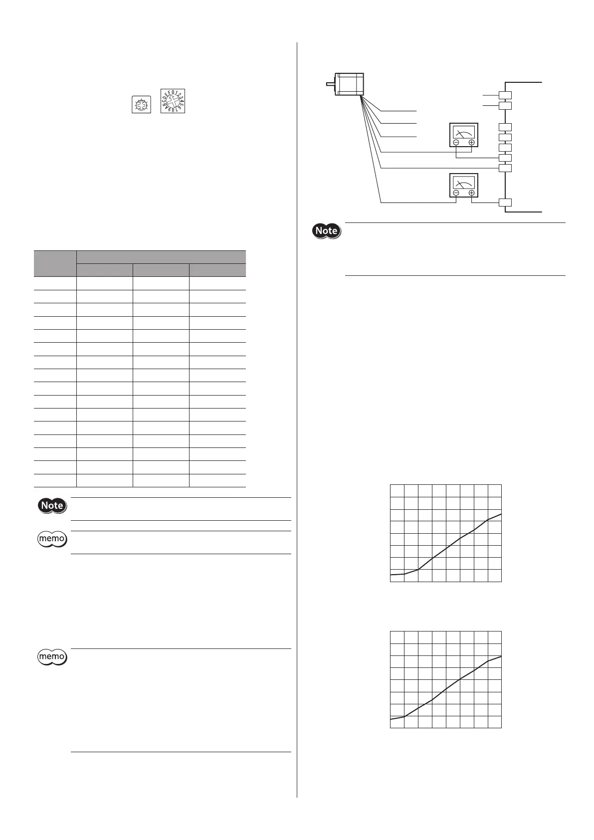
Setting method
Set the motor standstill current using ammeters.
Blue
Red
White
Green
Yellow
Black
GND
24 VDC±10%
Motor leads color
CN1
CN3
*
*
*
+
1
2
3
4
6
5
−
y
Check the colors of motor lead wires and connect them correctly
and securely. Wrong connection of lead wires or poor contact may
damage the driver.
y
Contacting blue, white and red lead wires of the motor (*) may result
in damage to the motor. Provide insulation measures for protection.
1. Connect a DC ammeter to motor.
2. Turn on the driver’s power supply.
3. Use an insulated precision screwdriver to turn the motor standstill current
potentiometer (STOP) to adjust the standstill current.
The sum of readings on two ammeters represents the current for one
phase.
Example:
Use
CMD2109P
at an operating current of 0.95 A/phase.
· When the motor standstill current potentiometer (STOP) is set to “2,” the
applicable standstill current is calculated as follows:
0.95 A/phase × 10% = Approximately 0.095 A/phase
· When the motor standstill current potentiometer (STOP) is set to “5,” the
applicable standstill current is calculated as follows:
0.95 A/phase × 36% = Approximately 0.35 A/phase
y
CMD2109P
[Representative values]
0
10
20
30
40
50
60
70
1 234567
8
STOP potentiometer
Current-cutback ratio (%)
y
CMD2112P
[Representative values]
0
10
20
30
40
50
60
70
1
2345678
STOP potentiometer
Current-cutback ratio (%)
 Loading...