Models of applicable motors
PK543N WA, PK544N WA, PK545N WA
PK564N WA, PK566N WA, PK569N WA
PK596-N A, PK599-N A, PK5913-N A
6
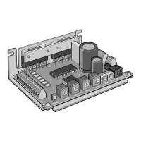
Preparation
This section covers the points to be checked, along with the names
and functions of respective parts.
Open the package, check the driver’s model number and confirm
that the operating manual is provided.
If the product is damaged or different from what you’ve ordered, con-
tact the branch or sales office from which you purchased the prod-
uct.
This driver can be used with 5-phase stepping motors with 5leads
connected in a New Pentagon method, as shown in the table below.
The motor operating current of the driver is set to 1.4 A/phase for
TD514-V
and 2.8 A/phase for
TD528-V
.
To drive a motor with an operating current of 0.75 A/phase, the mo-
tor current setting must be changed. See page 16
Driver 1 unit Operating manual 1 copy
HP-021
5-Phase Stepping Driver with Built-in Oscillator
TDSeries
Type V
(potentiometer type)
OPERATING MANUAL
Thank you for purchasing an Oriental Motor product.
This operating manual describes product handling
procedures and safety precautions.
●
Please read it thoroughly to ensure safe operation.
●
Always keep the manual where it is readily available.
P
O
W
E
R
S
P
E
E
D
A
C
C
E
L
D
E
C
E
L
J
-
L
I
M
R
U
N
S
T
O
P
O
/
P
1
S
H
O
T
O
F
F
C
D
1
2
3
O
N
1
1
Introduction ……………………………2
Safety precautions…………………… 3
Precautions for use ………………… 5
Preparation …………………………… 6
Checking the product……………… 6
Applicable motors ………………… 6
Names and functions of parts ……7
Installation …………………………… 8
Location for installation …………… 8
Installation method …………………8
Connection ……………………………9
Power connection ………………… 9
Motor connection……………………9
I/O Connection ……………………10
Connection of I/O …………………11
Explanation of I/O …………………12
Timing chart ………………………14
Setting …………………………………15
Setting of operating speeds and
acceleration/deceleration rates …15
Switch settings ……………………16
Setting of motor currents …………17
Overvoltage protection function ……19
Inspection ……………………………20
Troubleshooting and
corrective actions……………………20
Specifications ………………………22
Dimensional drawing ………………23
Table of Contents
POW
E
R
S
PE
ED
ACC
EL
D
EC
EL
J-LIM
RU
N
S
TOP
O
/P
1S
HO
T
O
FF
CD
1
2
3
O
N
1
1
Driver model
TD514-V
TD528-V
Motor current
0.75 A/phase
1.4 A/phase
2.8 A/phase
Enter A (single shaft) or B (double shaft) in the in the motor’s model number.
Checking the product
Applicable motors
19
Overvoltage protection function
When the driver’s inverter voltage exceeds a specified value, the dri-
ver’s overvoltage protection function is activated to immediately stop
the motor while causing the POWER LED to blink.
After the overvoltage protection function has been activated, remove
the cause, turn off the power and then turn it on again. The protection
function will be cancelled and the driver will return to its normal state.
●
When the driver’s protection function is activated, remove the
cause of the problem, and turn the power back on. Allowing
the driver to continue operating without removing the cause of
the problem may lead to motor or driver malfunction, resulting
in injury or equipment damage.
 Loading...