13
5.4
5.4
5.4
5.4 Introduction
Introduction
Introduction
Introduction to
to
to
to Port
Port
Port
Port board
board
board
board
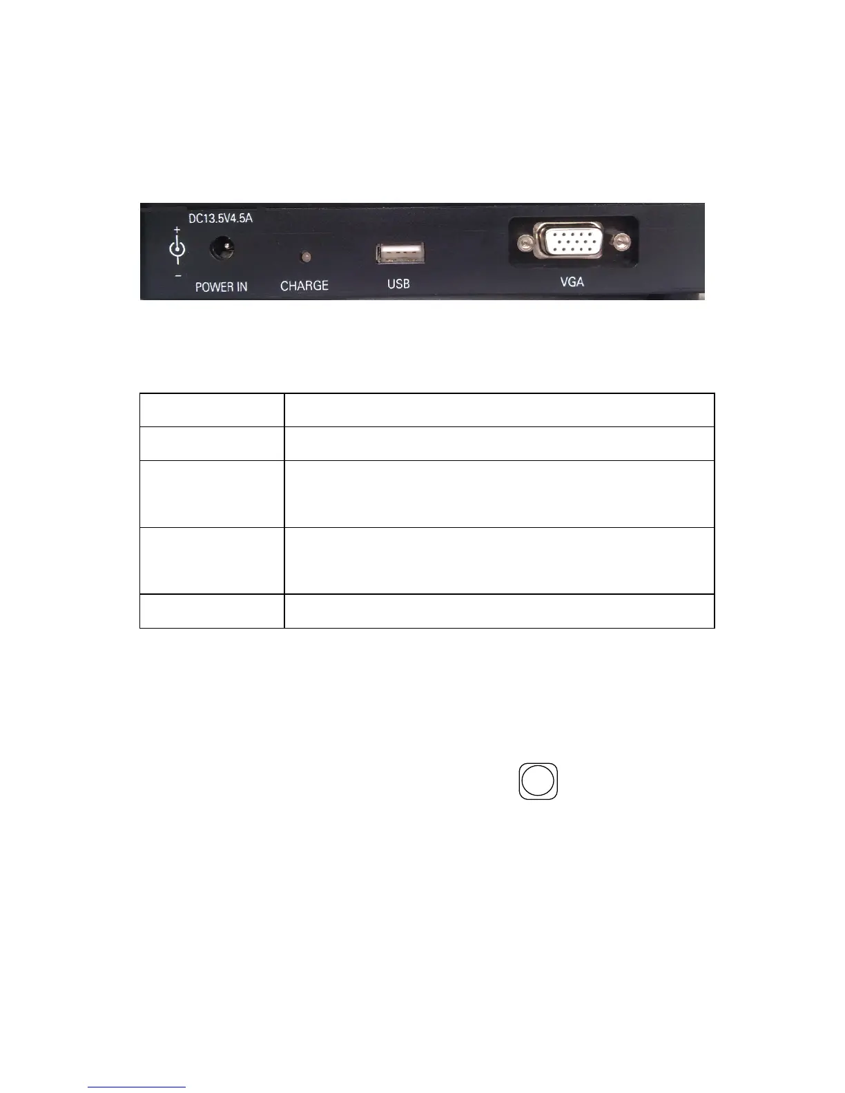
Input/Output port is on the right side of the main body, as figure
5-3 , the function are introduced in table 5-4.
Figure 5-3
Table 5-4
Name
Function Description
POWER IN
DC power input terminal,14.5V,45A.
CHARGE
W hen the lamp is red, the battery is charging .
When the lamp is off, the battery is full.
USB
Used to upgrading software and export ing
record data.
VGA
Video signal output.
5.5
5.5
5.5
5.5 Introduction
Introduction
Introduction
Introduction to
to
to
to Standby
Standby
Standby
Standby Interface
Interface
Interface
Interface
The standby interface and introduction of this OFFS is shown
in figure 2-2. And the standby interface can be switched to the
mode shown in figure 2-3 with the key
X - Y / -
. The image of
fibers, current fusion programme, battery capacity, the inner
temperature, inner humidity, the date and time are displayed on
the screen.