7
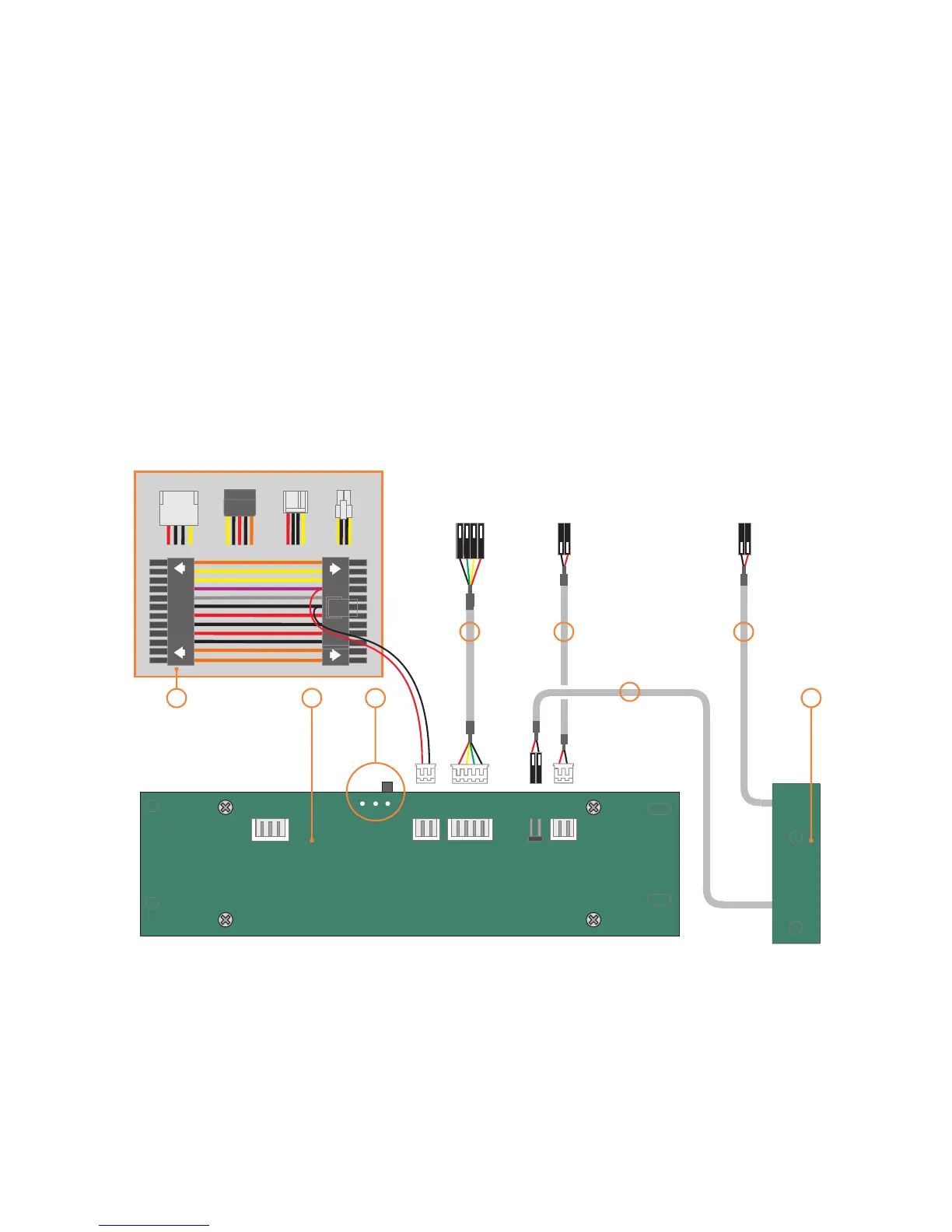
VF310 cable reference diagram
This is a general overview illustrating how the
internal PCBs interconnect. The VFD should be
switched to ‘S-GRAPH’ by default, which uses
the built in IR controller. Please refer to your
motherboard manual for the location of the
correct ports and header pins.
M-PWBT-P1
PHILLIPS
S-GRAPH
PHILLIPS
USB
STBY
POWER
IN OUT
VF310
5V STBY
GND
VCC
D-
D+
GND
PWR
SWITCH
To USB
Header
To Motherboard
On/Off Header
To Motherboard
SYSTEM LED Header
1 - VFD/IR module (VF310)
2 - IR selector switch ( )
3 - Main power button PCB (M-PWBT-P1)
4 - Standby ATX power cable (M-ATXS-C1)
5 - Internal USB cable (M-IUSB-C1)
6 - Power on/off cable (M-IPSW-C1)
7 - System LED cable (M-SLED-C1)
S-GRAPH is default
2
DC to DC
24Pin on M/B
1 3
4
5
4
6
7
6