EasyManua.ls Logo

Original Prusa MINI+ - User Manual

Default Icon
28 pages
Print Icon
To Next Page IconTo Next Page
Loading...
1
Table of Contents
Building your MINI+ 3 ...........................................................................................................
Step 1 - Preassembled vs kit version 4 ...........................................................................
Step 2 - Different hardware revisions 4 .........................................................................
Step 3 - All the required tools are included 4 ...............................................................
Step 4 - Use labels for reference 5 .................................................................................
Step 5 - We are here for you! 5 .......................................................................................
Step 6 - XYZ-axes parts preparation 5 ..........................................................................
Step 7 - XYZ-axes parts preparation 6 ...........................................................................
Step 8 - Foam pads - preparation 6 ...............................................................................
Step 9 - Foam pads installation 6 ...................................................................................
Step 10 - Opening the box with the electronics 7 ........................................................
Step 11 - Connecting the LCD cable 7 ............................................................................
Step 12 - Connecting the Y and XZ-axis assembly 7 ..................................................
Step 13 - Joining the parts together - preparation 8 ...................................................
Step 14 - Protecting the LCD cable 8 .............................................................................
Step 15 - Joining the parts together - phase 1 8 ...........................................................
Step 16 - Joining the parts together - phase 2 9 ..........................................................
Step 17 - Joining the parts together - phase 3 9 ..........................................................
Step 18 - Aligning the XZ-axis assembly 9 ...................................................................
Step 19 - Final tightening 10 ............................................................................................
Step 20 - Haribo time! 10 .................................................................................................
Step 21 - LCD parts preparation 10 ................................................................................
Step 22 - Mounting the LCD 11 .......................................................................................
Step 23 - Connecting the LCD 11 ....................................................................................
Step 24 - Guiding the LCD cable 11 ...............................................................................
Step 25 - Connecting the Y-axis motor 12 ....................................................................
Step 26 - Connecting the heatbed cable 12 ..................................................................
Step 27 - Filament sensor (optional) 12 .........................................................................
Step 28 - Filament sensor installation (optional) 13 ....................................................
Step 29 - Connecting the filament sensor (optional) 13 .............................................
Step 30 - Covering the electronics 13 ............................................................................
Step 31 - Haribo time! 14 ..................................................................................................
Step 32 - Spool holder parts preparation 14 .................................................................
Step 33 - Spool holder parts preparation 14 .................................................................
Step 34 - Assembling the spool holder base(s) 15 .......................................................
Step 35 - Adding the spool holder rails 15 ....................................................................
Step 36 - Adjusting the spool holder width 15 .............................................................
Step 37 - Attaching anti-slip pads 16 .............................................................................
Step 38 - Haribo time! 16 ..................................................................................................
Step 39 - Finalising the assembly 16 .............................................................................
Step 40 - Connecting the PSU 17 ...................................................................................
Step 41 - What is next? 17 ................................................................................................
Manual changelog MINI+ semi-assembly 18 ...............................................................
Step 1 - Version history 19 ................................................................................................
Step 2 - Changes to the manual (1) 19 ...........................................................................
Step 3 - Changes to the manual (2) 20 ..........................................................................
Step 4 - Changes to the manual (3) 20 ..........................................................................
Step 5 - Changes to the manual (4) 21 ...........................................................................
Step 6 - Changes to the manual (5) 21 ..........................................................................

Table of Contents

Question and Answer IconNeed help?

Do you have a question about the Original Prusa MINI+ and is the answer not in the manual?

Summary

Building your MINI+

Step 1 Preassembled vs kit version

Compares preassembled and kit versions of the MINI+ 3D printer.

Step 2 Different hardware revisions

Details variations in hardware revisions for the MINI+ printer.

Step 3 All the required tools are included

Confirms that all necessary tools for assembly are provided.

Step 4 Use labels for reference

Advises using labels for easier part identification during assembly.

Step 5 We are here for you!

Offers support and resources for assembly assistance.

Step 6 XYZ-axes parts preparation

Guides the preparation of parts for the X, Y, and Z axes.

Step 7 XYZ-axes parts preparation

Continues the preparation steps for the XYZ axes components.

Step 8 Foam pads - preparation

Instructions for preparing the foam pads for installation.

Step 9 Foam pads installation

Details the correct method for installing the foam pads.

Step 10 Opening the box with the electronics

Step-by-step guide to opening the electronics enclosure.

Step 11 Connecting the LCD cable

Instructions for connecting the cable to the LCD screen.

Step 12 Connecting the Y and XZ-axis assembly

Guides the connection of the Y and XZ axis assemblies.

Step 13 Joining the parts together - preparation

Preparation steps before joining major printer components.

Step 14 Protecting the LCD cable

Instructions on how to protect the LCD cable during assembly.

Step 15 Joining the parts together - phase 1

First phase of joining the main printer parts.

Step 16 Joining the parts together - phase 2

Second phase of joining the main printer parts.

Step 17 Joining the parts together - phase 3

Third phase of joining the main printer parts.

Step 18 Aligning the XZ-axis assembly

Guidance on aligning the XZ-axis assembly for proper function.

Step 19 Final tightening

Instructions for the final tightening of screws and components.

Step 20 Haribo time!

A break or reward step, often symbolic.

Step 21 LCD parts preparation

Preparation steps for the LCD screen components.

Step 22 Mounting the LCD

Instructions for physically mounting the LCD screen onto the printer.

Step 23 Connecting the LCD

Guides the electrical connection of the LCD screen.

Step 24 Guiding the LCD cable

Proper routing and management of the LCD cable.

Step 25 Connecting the Y-axis motor

Instructions for connecting the motor for the Y-axis.

Step 26 Connecting the heatbed cable

Guides the connection of the cable for the heated bed.

Step 27 Filament sensor (optional)

Introduction to the optional filament sensor.

Step 28 Filament sensor installation (optional)

Steps for installing the optional filament sensor.

Step 29 Connecting the filament sensor (optional)

Guides the electrical connection of the optional filament sensor.

Step 30 Covering the electronics

Instructions for covering the main electronics compartment.

Step 31 Haribo time!

A break or reward step, often symbolic.

Step 32 Spool holder parts preparation

Preparation of components for the spool holder assembly.

Step 33 Spool holder parts preparation

Further preparation of parts for the spool holder.

Step 34 Assembling the spool holder base(s)

Guides the assembly of the spool holder base structure.

Step 35 Adding the spool holder rails

Instructions for attaching the rails to the spool holder.

Step 36 Adjusting the spool holder width

How to adjust the spool holder to fit different spool widths.

Step 37 Attaching anti-slip pads

Steps for attaching anti-slip pads to the printer base.

Step 38 Haribo time!

A break or reward step, often symbolic.

Step 39 Finalising the assembly

Final steps to complete the printer assembly.

Step 40 Connecting the PSU

Instructions for connecting the Power Supply Unit.

Step 41 What is next?

Information on what to do after assembly is complete.

Manual changelog MINI+ semi-assembly

Step 1 Version history

Overview of the version history for the MINI+ semi-assembly manual.

Step 2 Changes to the manual (1)

Details the first set of changes made to the assembly manual.

Step 3 Changes to the manual (2)

Details the second set of changes made to the assembly manual.

Step 4 Changes to the manual (3)

Details the third set of changes made to the assembly manual.

Step 5 Changes to the manual (4)

Details the fourth set of changes made to the assembly manual.

Step 6 Changes to the manual (5)

Details the fifth set of changes made to the assembly manual.

Overview

This document serves as a comprehensive manual for the semi-assembly of the Original Prusa MINI+ 3D printer, guiding users through the process from unboxing to final setup. The manual is structured into two main sections: "Building your MINI+" which covers the step-by-step assembly, and "Manual changelog MINI+ semi-assembly" which details revisions to the manual itself.

Function Description:

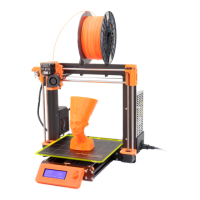
The Original Prusa MINI+ is a compact, semi-assembled 3D printer designed for both beginners and experienced users. Its primary function is to create three-dimensional objects from digital designs using Fused Deposition Modeling (FDM) technology. The semi-assembled nature means that critical components are pre-built, simplifying the assembly process for the user while still providing an engaging build experience. The printer features an integrated LCD screen for user interaction, a heatbed for improved print adhesion, and the option for a filament sensor to enhance reliability during printing. The design emphasizes ease of use, maintainability, and consistent print quality, characteristic of Prusa Research products.

Usage Features:

The assembly process for the Prusa MINI+ is broken down into numerous, manageable steps, ensuring a clear and guided experience.

  • Initial Setup and Preparation:

    • Preassembled vs. Kit Version: The manual begins by clarifying the difference between a fully preassembled unit and the semi-assembled kit, setting expectations for the user.
    • Hardware Revisions: It acknowledges potential variations in hardware revisions, indicating that the manual is designed to accommodate these differences.
    • Tools Included: All necessary tools for assembly are provided, eliminating the need for users to acquire additional equipment. This includes various Allen keys and an 8x10 mm wrench.
    • Labels for Reference: The use of labels for identifying parts is highlighted, streamlining the component identification process.
    • Support System: The manual emphasizes the availability of support resources, including online forums and a knowledge base, to assist users during assembly.
    • XYZ-Axes Parts Preparation: The initial steps involve preparing the XYZ-axes components, which are crucial for the printer's movement system. This includes handling the main printer body and associated parts.
    • Foam Pads Preparation and Installation: Foam pads are prepared and installed on the base of the printer, likely for vibration dampening and stability.
  • Electronics Integration:

    • Opening the Electronics Box: Users are guided to open the enclosure housing the printer's electronics.
    • Connecting the LCD Cable: The LCD cable is connected to the main electronics board, enabling the display functionality.
    • Connecting Y and XZ-axis Assembly: The Y-axis and XZ-axis assemblies are connected, integrating the primary motion systems with the electronics.
    • Joining Parts Together (Phases 1-3): The manual details a multi-phase process for physically joining the main printer components, ensuring proper alignment and secure connections.
    • Protecting the LCD Cable: Instructions are provided to protect the LCD cable, likely involving routing or securing it to prevent damage during operation.
    • Aligning the XZ-axis Assembly: Precise alignment of the XZ-axis is a critical step to ensure accurate printing.
    • Final Tightening: After initial assembly, a final tightening step ensures all connections are secure.
  • User Interface and Peripheral Connections:

    • LCD Parts Preparation and Mounting: The LCD screen components are prepared and then mounted onto the printer frame.
    • Connecting and Guiding the LCD Cable: The LCD cable is connected to the mounted screen and carefully guided to prevent interference or damage.
    • Connecting Y-axis Motor: The motor responsible for Y-axis movement is connected to the electronics.
    • Connecting the Heatbed Cable: The heatbed cable is connected, enabling the heated print surface.
    • Filament Sensor (Optional) Installation and Connection: For users opting for the filament sensor, detailed steps are provided for its installation and connection, enhancing print reliability by detecting filament run-out.
    • Covering the Electronics: The electronics enclosure is closed and secured, protecting the internal components.
  • Spool Holder Assembly:

    • Spool Holder Parts Preparation: Components for the filament spool holder are prepared.
    • Assembling the Spool Holder Base(s): The base structure of the spool holder is assembled.
    • Adding Spool Holder Rails: The rails, which support the filament spool, are attached to the base.
    • Adjusting Spool Holder Width: The width of the spool holder can be adjusted to accommodate different filament spool sizes.
    • Attaching Anti-slip Pads: Anti-slip pads are attached to the spool holder, ensuring stability during filament unwinding.
  • Final Steps:

    • Finalizing the Assembly: This step encompasses any remaining minor adjustments or checks to complete the physical assembly.
    • Connecting the PSU: The Power Supply Unit (PSU) is connected to the printer, providing power to the system.
    • What is Next?: The manual concludes by directing users to further resources, such as the 3D Printing Handbook and the Prusa Knowledge Base, for post-assembly setup, calibration, and printing guidance.

Maintenance Features:

While the manual primarily focuses on assembly, several steps implicitly or explicitly contribute to the maintainability of the device:

  • Clear Component Identification: The use of labels for reference during assembly aids in future troubleshooting and part replacement, as components are clearly identified.
  • Structured Wiring: Steps like "Protecting the LCD cable" and "Guiding the LCD cable" ensure that wiring is neatly routed and secured, reducing the risk of wear, damage, and making future access for maintenance easier.
  • Modular Design: The breakdown of the printer into distinct assemblies (e.g., XYZ-axes, electronics box, spool holder) suggests a modular design. This modularity simplifies maintenance and repair, as individual components or assemblies can be more easily accessed, diagnosed, and replaced without disassembling the entire printer.
  • Optional Filament Sensor: The optional filament sensor is a maintenance-enhancing feature, as it prevents failed prints due to filament run-out, thereby reducing material waste and the need for reprinting.
  • Access to Electronics: The "Opening the box with the electronics" step implies that the electronics are designed to be accessible for potential upgrades, diagnostics, or repairs.
  • Adjustable Spool Holder: The ability to adjust the spool holder width allows for compatibility with various filament spools, which can be seen as a maintenance feature that extends the printer's versatility and reduces the need for custom spool solutions.
  • Anti-slip Pads: The anti-slip pads on the spool holder contribute to the overall stability of the printer, which can indirectly reduce wear and tear on components that might otherwise be subjected to excessive movement or vibration.
  • Haribo Time!: The inclusion of "Haribo time!" at various stages serves as a lighthearted break, but also implicitly encourages users to take their time and avoid rushing, which can lead to errors and potential damage requiring maintenance.
  • Documentation and Support: The emphasis on the "3D Printing Handbook" and the "Prusa Knowledge Base" provides users with comprehensive resources for ongoing maintenance, troubleshooting, and optimal operation of their printer. This includes guides on calibration, cleaning, and general upkeep.
  • Manual Changelog: The "Manual changelog MINI+ semi-assembly" section is a direct maintenance feature for the documentation itself, ensuring that users always have access to the most up-to-date and accurate assembly instructions, which is crucial for correct initial setup and subsequent adjustments.

Original Prusa MINI+ Specifications

General IconGeneral
Build Volume180 x 180 x 180 mm
Layer Height0.05 - 0.35 mm
Filament Diameter1.75 mm
Nozzle Diameter0.4 mm
Max Print Speed200 mm/s
Max Nozzle Temperature280 °C
Max Bed Temperature100 °C
ConnectivityUSB, Ethernet
Display2.8'' color LCD
Supported MaterialsPLA, PETG, ABS, Flex
Power Input100-240 V AC, 50/60 Hz
Dimensions380 x 330 x 380 mm

Related product manuals