Other Checks
Space Temperature Sensor
If the Space Temperature Sensor is not reading a valid temperature,
rst make sure that the modular cable connector is rmly plugged into
the mating female modular connectors on the board and at the Space
Temperature Sensor. Also make sure if a cable coupler is used, that it is
rmly connected. If the problem persists, try swapping the sensor with
a known good Space Temperature Sensor. If that sensor works when
connected to the VAV/Zone Controller board, you can assume you have
a defective or damaged sensor.
Supply Air Temperature Sensor
If you suspect the Supply Air Temperature Sensor is not reading cor-
rectly, make sure the wiring terminal connections are tight and that any
wiring splices are properly connected. You can check the operation
of the Supply Air Temperature Sensor by measuring the resistance or
voltage using a digital multimeter. Set the meter to DC Volts. Place the
positive probe on the AIN terminal and the negative probe on the GND
terminal. Read the DC Volts and nd that voltage in Table 4. Read the
temperature corresponding with that voltage and determine if this is close
to the actual temperature the sensor is exposed to. If the temperature from
the chart is different by more than a few degrees, you probably have a
defective or damaged sensor. You can also check the sensor resistance
to determine correct operation. To read the resistance, set the meter to
Ohms. Unplug the sensor connector from the board and measure the
resistance across the disconnected wires. This resistance should match
the corresponding temperature from Table 4.
Airow Sensor
If the Airow Sensor seems to be reading incorrectly, rst check the
Airow Sensor’s modular cable connector and be sure it is rmly con-
nected to its mating connector on the VAV/Zone Controller board.
Check the Airow Sensor tubing connections at the airow pickup
tubes. The high pressure port of the sensor needs to be connected to
the upstream pickup tube. The low pressure port of the sensor needs to
be connected to the downstream pickup tube.
The “Air Valve Sizing Constant” setting under the conguration settings
for the VAV/Zone Controller must be set to a number other than 0. This
number is normally referred to as the “K” factor and is supplied by the
terminal unit manufacturer. It represents the airow through the box inlet
at 1” W.G. constant static pressure. This factor must be entered in the
conguration screen or the airow through the box will be incorrect.
If none of the aforementioned procedures solves the problem, remove
power from the VAV/Zone Controller. Shut down the HVAC unit sup-
plying the duct that the VAV/Zone damper is located on. Be sure that no
airow is present in the duct. Reapply power to the board and wait for
the VAV/Zone Controller to run through its calibration sequence. Restart
the HVAC unit and check the VAV/Zone Controller CFM readings. If the
CFM reading still seems to be in error, you probably have a defective
Airow Sensor and will need to replace it.
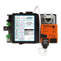
Actuator
Check the Modular cable between the controller and the actuator. Be sure
both ends of the cable are rmly connected to the mating connectors on
the actuator and the VAV/Zone Controller board. Be sure the damper
moves freely and is not bound. Do this by pressing the actuator clutch
button and rotating the damper shaft in both directions to verify smooth
operation. If binding is present, x the problem as required. Remove
power from the VAV/Zone Controller. Reapply power and observe
the damper rotation. If the actuator does not drive the damper in both
directions, the actuator is probably defective or damaged. Another test
that can be performed is to swap cables with another known operating
actuator to determine if the cable could be bad. If the problem goes
away, you have a defective cable that must be replaced. You can also try
swapping a functioning actuator with the suspected defective actuator. If
this solves the problem, the defective actuator will need to be replaced.
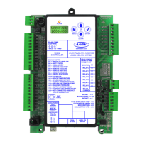
Expansion Module
If the Expansion Module does not seem to operate correctly, rst make
sure the modular cable between the Expansion Module and the Non-
Modular VAV/Zone Controller Actuator Package is rmly connected
at both ends. Be sure that the Expansion Module has been congured
correctly. The expansion board must be congured using the Modular
Service Tool, Modular System Manager, System Manager TS, or Prism
computer software for your application before it will operate. You must
congure the number of heat stages, and if it is a fan terminal you must
congure whether it is a Series Flow or Parallel Flow Fan Terminal unit.
On a single duct non-fan terminal unit when a call for heat is initiated,
the LED labeled RLY2 should light up. If the Expansion Module is
congured as a fan terminal, on a call for the fan, the LED labeled RLY1
should light up. If the LEDs do not light up, the Expansion Module is
probably defective and must be replaced.
Diagnostics
29
Non-Modular ZCAP Technical Guide
Troubleshooting
 Loading...