Temperature Sensor Testing
Temperature Sensor Testing
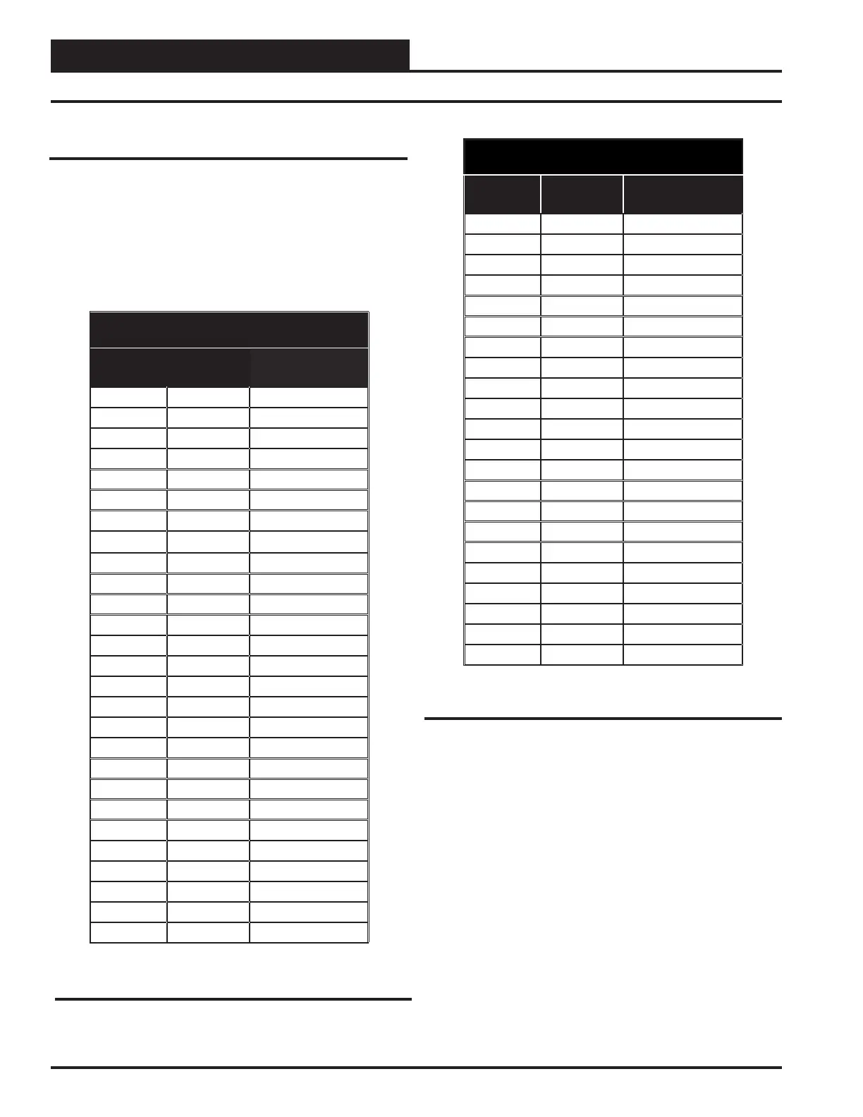
The following sensor voltage and resistance table is provided to aid in
checking sensors that appear to be operating incorrectly. Many system
operating problems can be traced to incorrect sensor wiring. Be sure all
sensors are wired per the wiring diagrams in this manual.
If the sensors still do not appear to be operating or reading correctly,
check voltage and/or resistance to conrm that the sensor is operating
correctly per the table. Please follow the notes and instructions in Figure
20 when checking sensors.
Table 4: Temperature/Resistance for Type III 10K
Ohm Thermistor Sensors
Temperature – Resistance – Voltage for
Type III 10 K Ohm Thermistor Sensors
Temp
(ºF)
Resistance
(Ohms)
Voltage @ Input
(VDC)
-10 93333 4.620
-5 80531 4.550
0 69822 4.474
5 60552 4.390
10 52500 4.297
15 45902 4.200
20 40147 4.095
25 35165 3.982
30 30805 3.862
35 27140 3.737
40 23874 3.605
45 21094 3.470
50 18655 3.330
52 17799 3.275
54 16956 3.217
56 16164 3.160
58 15385 3.100
60 14681 3.042
62 14014 2.985
64 13382 2.927
66 12758 2.867
68 12191 2.810
69 11906 2.780
70 11652 2.752
71 11379 2.722
72 11136 2.695
73 10878 2.665
Temperature – Resistance – Voltage for
Type III 10 K Ohm Thermistor Sensors
Temp
(ºF)
Resistance
(Ohms)
Voltage @ Input
(VDC)
74 10625 2.635
75 10398 2.607
76 10158 2.577
78 9711 2.520
80 9302 2.465
82 8893 2.407
84 8514 2.352
86 8153 2.297
88 7805 2.242
90 7472 2.187
95 6716 2.055
100 6047 1.927
105 5453 1.805
110 4923 1.687
115 4449 1.575
120 4030 1.469
125 3656 1.369
130 3317 1.274
135 3015 1.185
140 2743 1.101
145 2502 1.024
150 2288 0.952
Table 4, cont.: Temperature/Resistance for Type III
10K Ohm Thermistor Sensors
30
Non-Modular ZCAP Technical Guide
Troubleshooting
 Loading...