4
2. Assembly
1. After removing and identifying all the parts from the back-
pack (A), spread the legs of the tripod (B) and then tighten
the center post lock collar at the bottom of the post by turn-
ing the collar clockwise (Figure 3).
2. Extend the tripod legs to the desired length by ipping
open the leg lock clamps, extending the leg section, then
closing the leg lock clamps. The tripod should now appear
as in Figure 4.
3. To attach the optical tube (F) to the pan head, rst you
will need to remove the pan head’s quick-release plate
(Figure 5). To do that, push the lock lever outward 90
degrees. That unlocks the plate, which can then be lifted
out.
4. Attach the quick-release plate to the dovetail mounting
plate on the bottom of the optical tube (F), by screwing the
threaded post of the quick-release plate into the socket on
the optical tube mounting plate (Figure 6a). Use the small,
hinged D-ring on the underside of the quick-release plate
to turn the threaded post until tight.
5. Now with the quick-release plate installed on the tele-
scope optical tube, insert the plate into the pan head,
making sure the lock lever is in the unlocked, or open,
position. You may have to tilt the plate as shown in Figure
6b while inserting it into the pan head, in order to seat it
properly. Once the plate is fully seated, the lock lever can
be pressed back to the closed position, as shown in 6c.
6. Now you’ll assemble the nder scope. First locate the
clear plastic strip (C). Curl it and insert it into the nder
scope bracket (D), as shown in Figure 7. Then slide the
nder scope tube (E) eyepiece end rst, into the bracket
and inside the curled plastic strip. (Note that you should
make sure the three thumbscrews on the bracket are
loosened enough to allow the nder scope tube to pass
through freely.) When it is correctly inserted, the tube
should appear as in Figure 8, with the edge of the clear
plastic strip just showing. The plastic strip encircling the
nder scope tube stabilizes the front portion of the nder
scope in the bracket. Without the strip, the nder scope
would move around inside the bracket, which is not desir-
able.
7. Now remove the two thumbnuts on the telescope tube
to expose the two threaded posts. Then place the nder
scope bracket over the posts as shown in Figure 9. Then
thread on the thumbnuts and lightly tighten them to secure
the nder scope bracket in place.
8. Next, insert the 45-degree correct-image diagonal acces-
sory (G) into the focuser drawtube, making sure the two
thumbscrews are loosened enough to allow the diagonal’s
barrel to be fully inserted (Figure 10). Then tighten the two
thumbscrews.
9. Now insert the 20mm Kellner eyepiece (H) into the diag-
onal and tighten the thumbscrew to lock the eyepiece in
place (Figure 11).
The telescope is now completely assembled! Before it can be
effectively used, however, there are a couple of things to do to
prepare the telescope for operation.
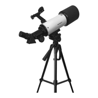
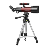
Figure 2. The GoScope III 70mm Travel Refractor telescope fully
assembled, with key parts identied.
A
E
H
D
B
F
G
Figure 3. Setting up the tripod.
Ballast
hook
Leg lock
clamps
Center
post lock
collar
 Loading...