4 IM0973142 R1-4 IM0973142 R1-4 5
Installation Manual
5. Electrical installation
The PTZ unit must be connected by trained electri-
cians. Under no circumstances should you make
connections that are not described in this manual.
5.1 PTZ Cable specifications. Cable Base, Art no 1221300
1 = Coax core Video
2 = Coax shielding Video GND
3 = Red Camera power, 18...30V/DC (fuse 315mA)
4 = Black Camera 0V
5 = Red/White Pan/Tilt power (fuse 500mA)
6 = Black/White Pan/Tilt 0V
7 = Green Serial 1 RS-232 TX
8 = Grey Serial 2 RS-232 RX
9 = Black/Gray Serial 0V
1 = Red/blue N.C.
2 = Black/blue N.C.
3 = Blue N.C.
4 = Brown N.C.
5 = Shield N.C.
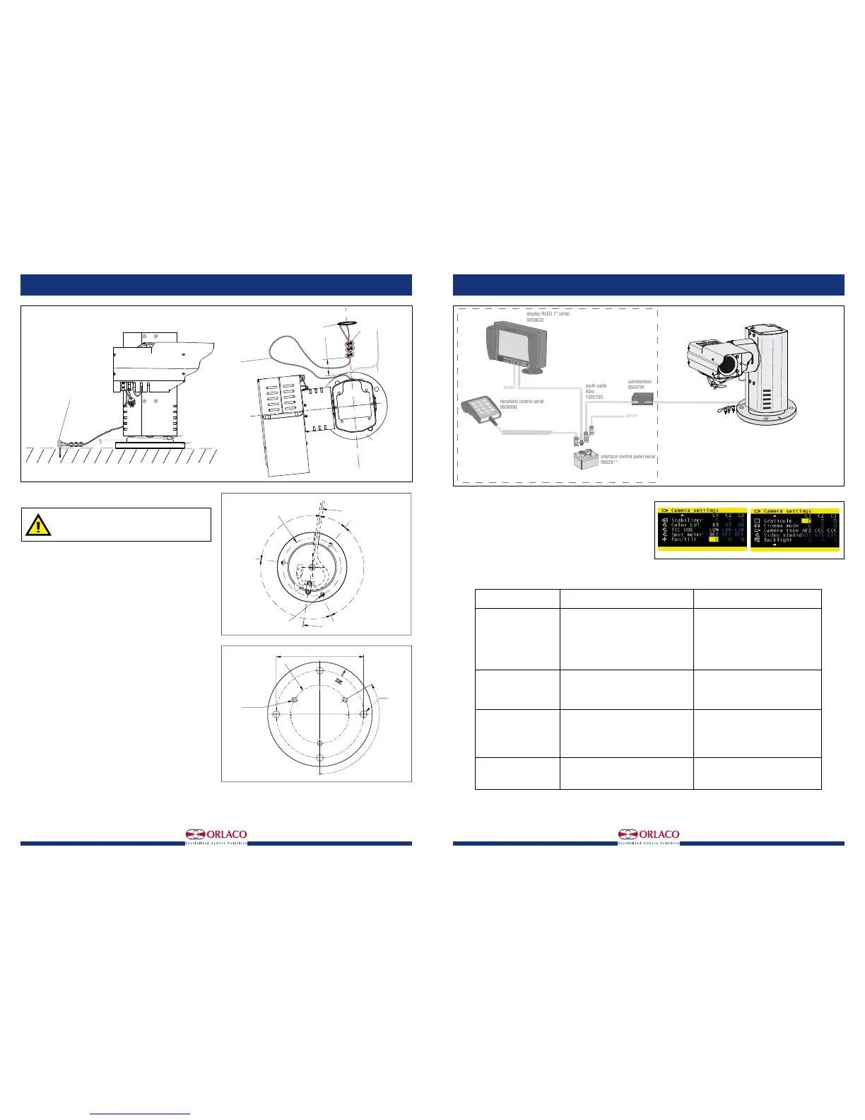
5.2 Example configuration
The following products are required for basic operation of the
PTZ unit,
see figure 7.:
PTZ unit Art Nr 0506910.
Monitor RLED 7", Art no 0208632.
Installation Manual
6. Instructions for use
Using the Monitor: See User Manual IM0972080 Monitor 7" RLED/LEDD
for detailed instructions about how to use the Monitor
To set the PTZ unit and the autofocus function, go to the camera settings
area via the service menu; then select ‘Pan/tilt’ to operate the PTZ unit
from the keyboard and select ‘AFZ’ for the zoom camera functions. See
figure 8.
7. Troubleshooting
power
power
display RLED 7” serial
0208632
handheld control serial
0506950
interface control panel serial
05029**
multi cable
40m
1220150
Junctionbox
0504791
Camera PTZ Sst
0506910
optional
Cable Base
Art.No. 1221300
Lenght 3,6m
Figure 7
R = 50,0
M8 x 1,25 (3x)
horizontal zero position
Cable
120°
90°
30°
120°
Base
back side
120° (3x)
M8 (3x)
R = 50,0
∅12 (4x)
Figure 6
Problem
1. Monitor does not work.
2. Monitor has no picture.
3. Camera does not work.
5. PTZ does not work.
Possible cause
System is not switched on.
System is not connected or the supplied voltage
of the vehicle to which the system is connected
is too low (flashing LED on camera).
Fuse of the vehicle’s supply voltage is defective.
Other cause.
Monitor is not or incorrectly connected to the
control box.
Camera is not functioning.
Other cause.
Camera is not or incorrectly connected.
The camera is defective.
Other cause.
PTZ not or incorrectly connected to the camera.
Other cause.
Solution
Connect the Power cable to the right power
supply.
Connect the system and measure the vehicle’s
supplied voltage when the system is switched
on.
Replace the fuse.
Contact your Orlaco dealer.
Check the connection of the Monitor
See problem 3.
Contact your Orlaco dealer.
Check the connection of the PTZ to the opera-
ting panel and make sure the red LED on the
camera is lit.
Contact your Orlaco dealer.
Contact your Orlaco dealer.
Check the connection of the Monitor to the
camera.
Contact your Orlaco dealer.
Figure 8
R = 50,0
M8 x 1,25 (3x)
horizontal zero position
Cable
120°
90°
30°
120°
Base
back side
Base plate
Top side
150
120° (3x)
M8 (3x)
R = 50,0
∅12 (4x)
Figure 5
Camera cable
Top view
Base Plate
∅2 safety cable
from the camera
length 360-370
between camera
and wire rope
clamp
60 ±10
wire rope clamps (3x)
Mount the safety cable from
the camera on a fixed
mounting point on the same
surface and height as
the Base plate
Base plate
Camera cable
Top view
Base Plate
∅2 safety cable
from the camera
length 360-370
between camera
and wire rope
clamp
60 ±10
wire rope clamps (3x)
Mount the safety cable from
the camera on a fixed
mounting point on the same
surface and height as
the Base plate
Base plate
 Loading...