4
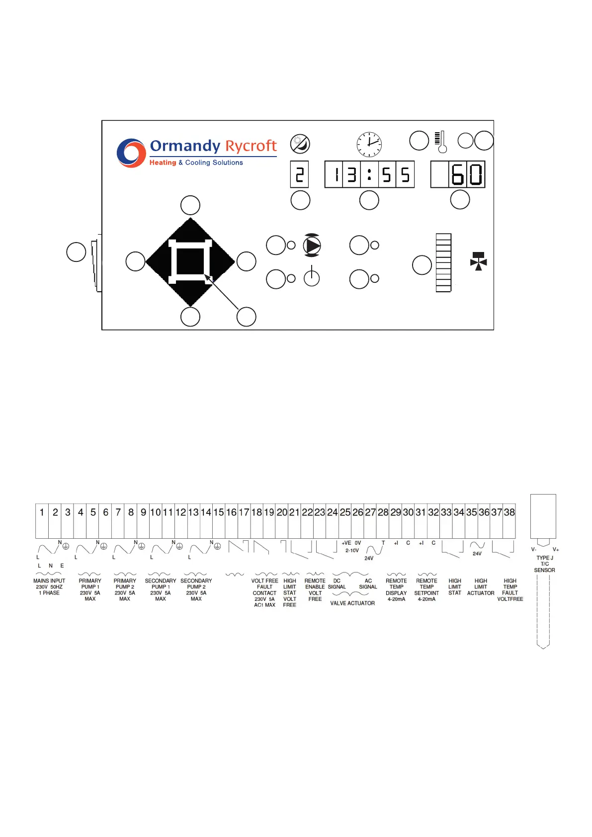
The Electrical connections are located in the terminal compartment. A description of the terminals can
be found on the inside of the terminal compartment cover.
Connectasinglephase230V50HzsupplytotheMainsInputterminals.Themaximumfullloadcurrent
is16A,withthemajorityofunitsbeingconsiderablyless.
Iftheunitistobecontrolledremotely,connecttheremotecontrolswitchorcontactstotheRemote
enableterminals.Iftheunitistobecontrolledlocally,talinkbetweentheseterminals.
Do NOT apply voltage to these terminals!
Voltage free fault relay contacts are provided for Remote Fault Indication.
13 System Healthy Indicator
14 System Fault Indicator
15 ValvePositionBarDisplay
16 On/Offswitch
1 Day/Mode Display
2 Time/Alarm Display
3 Temperature/Parameter Display
4 High Temperature Alarm Indicator
5 ResetPushButton
6 StepLeftPushButton
7 Value Increase Push Button
8 Step Right Push Button
9 Value Decrease Push Button
10 ModeSelectPushbutton
11 Pump Energised Indicator
12 PowerOnIndicator
Terminal Block
2.2 Operation and Set Up
Electrical Connections
Key to Ormandy Rycroft Breeze controls and indicators.
1 2
3
4 5
6
7
8
9 10
11
12
13
15
14
16
✓
✘
100
50
0
1
3
6
2
5
4
7
On/Off
Switch