Page 30 / 36
Hartley and Sugden
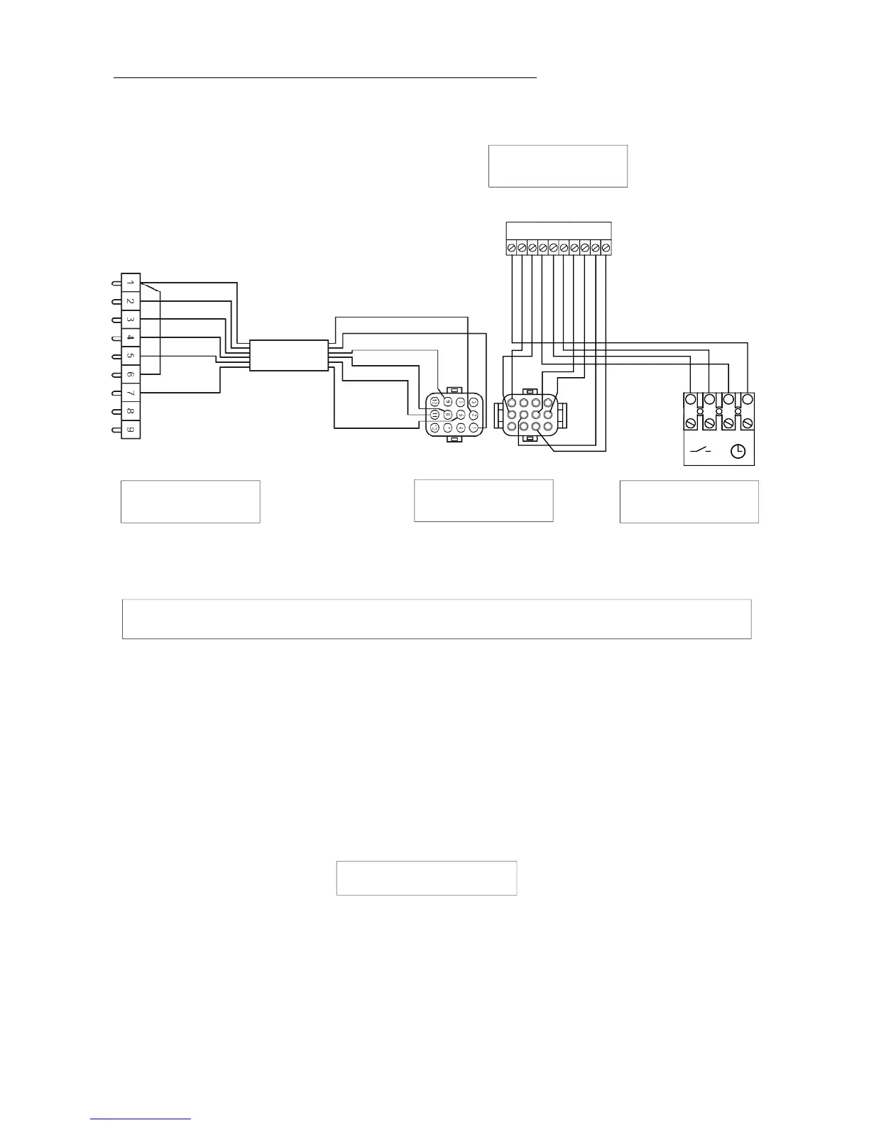
6. 1. 3 . Connection kit GTCO regulator
II
12
3
4
5678
9
10
NL1
1
4
7
10
2
5
8
3
6
9
1112
ST 2
GTC 0
CONNECTION OF THE GTC0 REGULATOR ON THE COMMODORE PLUS BOILERS RANGE
1. Remove the right cap on the c ontrol panel and engage the regulator in this housing.
2. Remove the 9 poles male connector with its 4 bridges on the back of the control panel, or remove the S.W.W. priority
Ventec module already connected.
3. Connect the 9 poles connector (A) boiler side delivered with the regulator in the 9 poles female connector block
of the boiler and tighten the screws.
Connect the AMP 12 poles connector (B) delivered with the regulator in the AMP 12 poles p lug of connector (A).
4. Connect the 10 poles white connector on the connector block II of the regulator.
5. Connect directly the following probes on the connector block I of the regulator.
- KFS : boiler probe
- SPFS : S.W.W. probe
6. Connect the heating circulator to terminals 8 and 9 and if necessary the S.W.W. circulator to terminals 11 and 12
on the boiler 12 poles connector block ( back of the control panel ).
GENERAL REMARKS
- do not connect the summer / winter switch anymore, neither the S.W.W. tank thermostat, these functions being ensured
directly by the GTC0 climatic r egulator.
- place the boiler thermostat instruction at 80°C approximately.
Room
thermostat
10-poles connector
regulator side
9-poles connector (A)
boiler side
AMP connector
12-poles (B)