Page 27 / 36
Hartley and Sugden
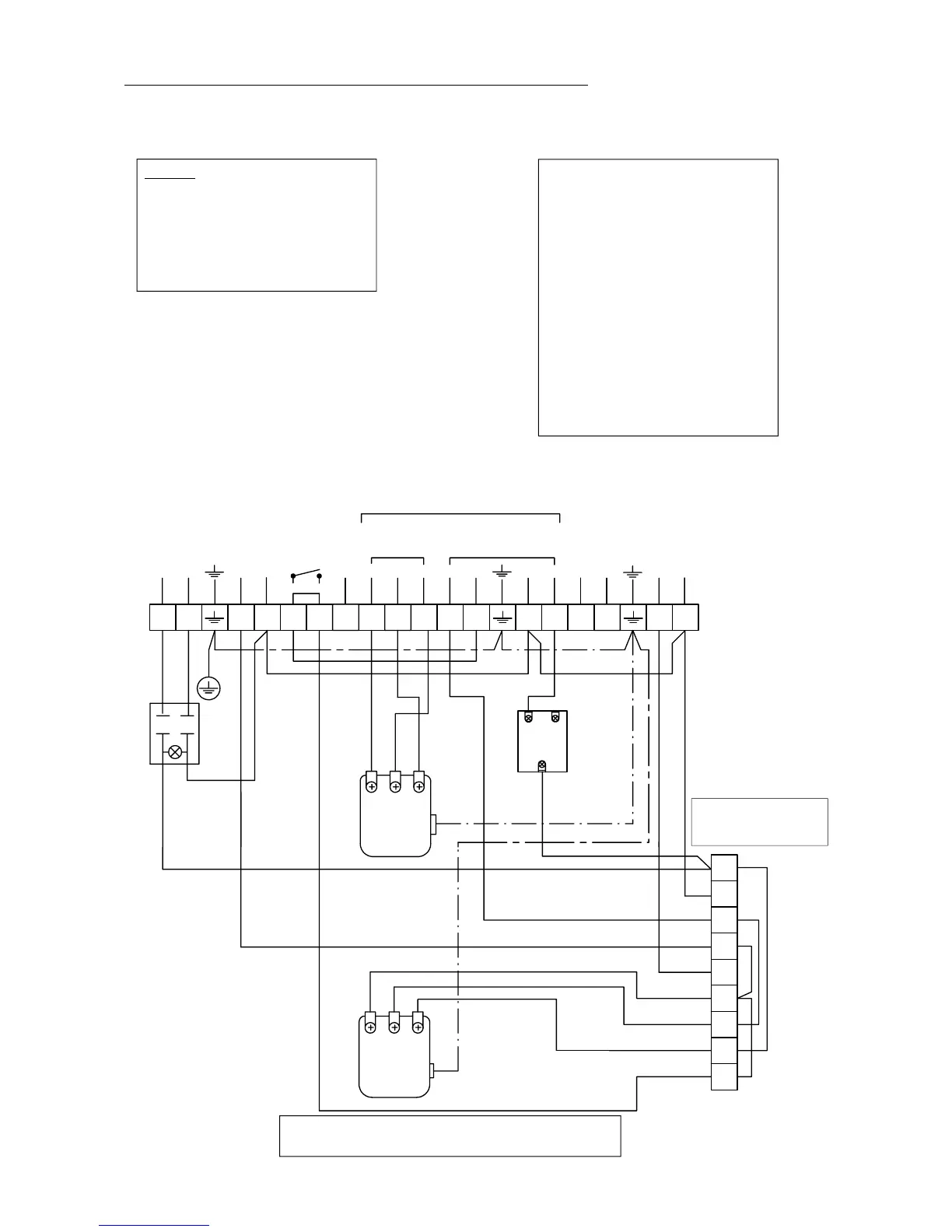
6. Electrical connections
Wiringdiagram:
The setting of the temperature on the
high/lowthermostat (f.i.65°C) hasto be
inferiorto thatof the first step thermos-
tat(f.i. 80°C).In thisway, ifthe boiler is
cold and if there is a heat demand, the
burner will start with its whole power
and once the 65°C reached, it will con-
tinue to burn with reduced power until
the water temperature of the flow rises
to 80°C. If the heat demand is to impor-
tant that the water temperature falls
down instead of reaching 80°C, than
the whole power will engage again.
Remark:
As far as Ecosets are concerned are the
electrical connections o f the circulation
pump of the heating circuit made in the
control box outisde the boiler control
panel.
T6
T7
T8
T2 T1
N
L1
L
N
21P
21P
4
1
5
2
P
1
2
23456789
1
12 4567891011 15 2021
L
N
L
N
1612
B4
B5
17
S3
13 18
To burner
Safety limit
SP-051 HE
(110°C)
230V ca-50Hz
NT 174 HE/2
2
nd
step
thermostat
(30 - 90°C)
Power supply
switch
with phial
Circ ulation pump
heating circuit
(not supplied)
Remote
thermostat
(not supplied)
Standard plug
with 3 poles
(not supplied)
Standard plug
with 7 poles
(not supplied)
Circ ulation pump
water tank
(not supplied)
Remove the 4 bridges
when you connect a digital
regulator E9. 0631
If you connect a regulator E9.0631, remove the bridge
between terminals 5 and 6 of the main connector block.
(*)
NT 174 HE/2
1
st
step
thermostat
(30 - 90°C)