IG-183-EN version 06; 31/03/2020
33
General instructions
cgm.3 system: medium voltage SF
6
gas-insulated
cubicles up to 38 kV according to IEEE and CSA standards
Installation
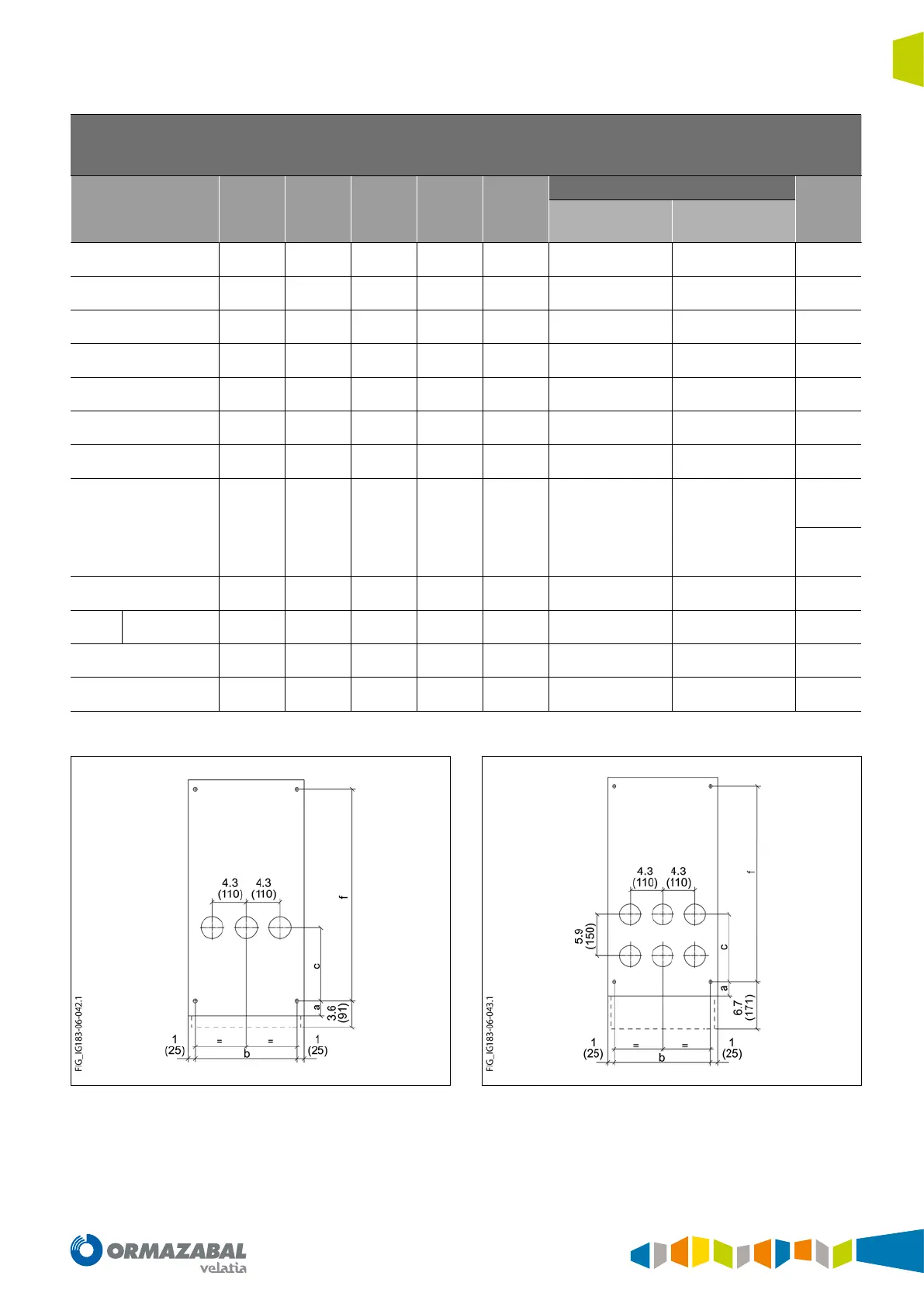
Anchoring dimensions
(inches)
[mm]
Module a b c d e
f
g
Internal arc up
to 0.5 s
Internal arc up
to 1 s
-l
(2)
[50]
(14)
[368]
(10)
[245]
- -
(21)
[540]
(28)
[710]
-
-s
(2)
[50]
(14)
[368]
- - -
(21)
[540]
(28)
[710]
-
-s-pt
(2)
[50]
(22)
[550]
- - -
(21)
[540]
(28)
[710]
-
-p
(2)
[50]
(17)
[430]
(2)
[60]
- -
(21)
[540]
(28)
[710]
-
-v
(2)
[50]
(22)
[550]
(13)
[325]
- -
(21)
[540]
(28)
[710]
-
-rb
(2)
[50]
(14)
[368]
(10)
[245]
- -
(21)
[540]
(28)
[710]
-
-rb-pt
(2)
[50]
(14)
[368]
(10)
[245]
- -
(21)
[540]
(28)
[710]
-
-rc
(2)
[50]
(12)
[317]
(17.13)
[435]
- -
(21)
[540]
(21)
[540]
-rci
(8)
[209]
-rci
(8)
[209]
-r2c
(2)
[50]
(19.68)
[500]
(17.13)
[435]
- -
(21)
[540]
-
(8)
[209]
-m
width 1100 mm -
(40)
[1030]
-
(7)
[176]
(17)
[427]
(40)
[1019]
(40)
[1019]
-
-2lp
(2)
[50]
(14)
[368]
(10)
[245]
(17)
[430]
(16)
[418]
(21)
[540]
(28)
[710]
(3)
[60]
-2lv/-rlv
(2)
[50]
(22)
[550]
(13)
[325]
(16)
[418]
- -
(28)
[710]
(3)
[60]
Table 4.9. Anchoring dimensions
Figure 4.13. Anchoring points in cubicles cgm.3 -l, -s, -s-ptd, -p, -v, -rb, -rb
with grounding
Figure 4.14. Anchoring points in cubicles cgm.3 -l, -s, -s-ptd, -p, -v, -rb, -rb
with grounding & double cable
 Loading...