Do you have a question about the Ormazabal cgm.3 system Series and is the answer not in the manual?
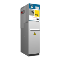
Details the primary components that constitute the cgm.3 switchgear cubicles.
Covers the mimic diagram and operational steps for the feeder function of the switchgear.
Explains the mimic diagram and operational procedures for the circuit-breaker function.
Details the mimic diagram and operation of the busbar switch function.
Provides steps for closing the busbar switch from the disconnected position.
Provides steps for opening the busbar switch from the closed position.
Covers mimic diagram and operations for the busbar switch with earth connection.
Provides steps for opening the busbar switch with earth connection from earthing.
Provides steps for connecting the switch-disconnector from the disconnected position.
Covers mimic diagram and operation procedures for the fuse protection function.
Detailed procedure for safely replacing blown fuses in the protection function.
Details the safety locks and interlocks that ensure correct and safe operation of the switchgear.
Specifies the required clearances from walls and ceiling for safe installation.
Explains methods for securely anchoring the cubicles to the installation floor.
Provides instructions for connecting the general earth collector for safety.
Explains how to connect medium voltage feeders via cables to the cubicles.
| Rated voltage | Up to 24 kV |
|---|---|
| Short-circuit current | Up to 25 kA |
| Operating temperature range | -25°C to +40°C |
| Enclosure material | Steel |
| Weight | Varies depending on configuration |