General instructions
Installation
IG-136-EN version 10; 23/06/2016
18
cgm.3 system
Fully SF6 gas insulated medium voltage switchgear up to 40.5 kV in accordance with IEC Standards
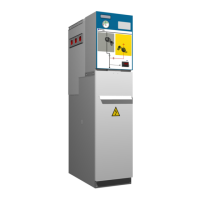
Figure 4.2 Location of accessories in cgm.3-l and cgm.3-v
cubicles
Depending on the cubicle model, the accessory box
contains some of the following items:
• General Instructions Document IG-136 by
Ormazabal.
• Driving lever
• Spring charge lever
• Cubicle connecting kit:
- ormalink
- Springs
- Syntheso grease
- Earthing bar
• End plug kit:
- Cubicle end assembly
- Nylon thread
- Plastic plugs
- Side cover
• Floor fastening assembly
4.3 Minimum installation distances
The minimum distances to the walls and ceiling which
must be maintained in the installation are as follows:
Figure 4.3 Minimum installation distances
Minimum distances [mm]
Side wall (a) 100
Roof (b)
Height 1400 mm 600
Height 1745 mm 550
Front clearance (c) 500 (*)
Function Rear wall (d)
cgm.3-l / -s / -v / -2lv / -rb / -rc
100 / 160(***)
cgm.3-p / -2lp
0
cgm.3-m without IAC
classification
0
cgm.3-m with IAC
classification
100 / 150(****)
(*) An operating clearance of at least 1000 mm is recommended.
(**) Cubicles with classification IAC AFLR: d = 800 mm.
(***) Diagrams combined with p and 2lp cubicles.
(****) For classification IAC 21 kA – 1 s.
The measurements indicated in the table
have been obtained in accordance with the
dimensions of the test room for the gas insulated
modules, in accordance with Annex AA of
Standard IEC 62271-200.
The space required to extend the assembly with an
additional cubicle is 250 mm plus the width of the new
cubicle
[7]
.
[7]
For any doubts, please ask Ormazabal.
 Loading...

