Do you have a question about the Ortur Y-axis and is the answer not in the manual?
Connect the frame and motor using specified screws (M3*8 and M5*10).
Attach the idle pulley with bearings, spacers, and nuts (M5).
Install rollers using bearings and M5*10 screws, reserving an installation gap.
Fit the 25-tooth and 16-tooth pulleys onto the roller assembly.
Launch LaserGRBL, connect to the engraver, and unlock its functions.
Access Grbl configuration to adjust parameters like disabling automatic return to origin.
Write the adjusted settings to the main board and close the configuration window.
Position object, connect roller to engraver using a 500MM extension cable.
Modify engraver height and laser focus for optimal engraving on the object.
Place object, connect roller to frame engraver, and adjust engraver height.
Ensure the laser spot aligns precisely with the apex of the cylindrical object.
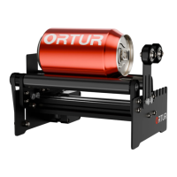
This document describes the Ortur Y-Axis Rotary Roller, an accessory designed for laser engraving cylindrical objects. It is an integral part of a laser engraver system and cannot be used independently.
The Ortur Y-Axis Rotary Roller facilitates laser engraving on cylindrical objects by providing a rotating platform. This allows the laser engraver to process the entire surface of a round item, such as a cup, bottle, or pipe, ensuring consistent engraving quality across its circumference.
The rotary roller is designed for integration with various laser engraver brands, though a perfect match is not guaranteed for non-Ortur engravers. Users are cautioned against modifying the device without permission, as this voids responsibility from the manufacturer.
Assembly Procedure: The assembly process involves several steps:
Setting Procedure (LaserGRBL Software): To use the rotary roller, specific settings must be configured in the LaserGRBL software:
Installation Methods:
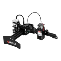
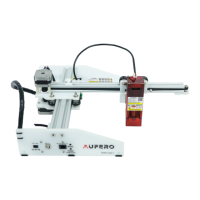
1. Cantilever Laser Engraver: * Place the object as shown in the figure, and connect the rotary roller to the laser engraver using a 500MM extension cable. * Unplug the Y Motor Cable from the engraver and connect it to the Y-axis Rotary Roller via the extension cable. * Heighten the laser engraver according to the height of the object being engraved. * Adjust the position and laser focus, then start engraving. * WARNING: Eye protection (laser goggles) must be worn before operating the laser.
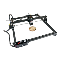
2. Frame Laser Engraver: * Place the object as shown in the figure, and connect the rotary roller to the laser engraver. * Heighten the laser engraver according to the height of the object. * Unplug the Y Motor Cable from the engraver and connect it to the Y-axis Rotary Roller via the extension cable. * Adjust the position and laser focus, then start engraving. * PS: Eye protection (laser goggles) must be worn before operating the laser. * The laser spot should be aligned with the apex of the cylindrical object for optimal engraving.
The manual provides details on the screws, nuts, bearings, spacers, and timing belt pulleys used in the assembly, indicating precise engineering for robust performance.
While explicit maintenance features are not detailed, the modular design with easily identifiable components (screws, nuts, bearings) suggests that parts can be replaced or adjusted if needed. The instruction to not tighten screws immediately during roller assembly implies a need for precise alignment, which is a common aspect of maintaining optimal performance in mechanical systems. Regular checks of belt tension and roller alignment would likely be beneficial for long-term operation.