POWER INPUT
POWER INPUT
3 Turnoffpower,stopmassage、
4 Installing the arm rests、
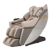
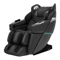
Method of usage Method of usage
·In the process of massage, press the power switch key to immediately turn off all
massage functions, the backrest and the calf are reset, the massage time is up,
and all massage functions are immediately turned off, and the backrest and the
calf are not reset.
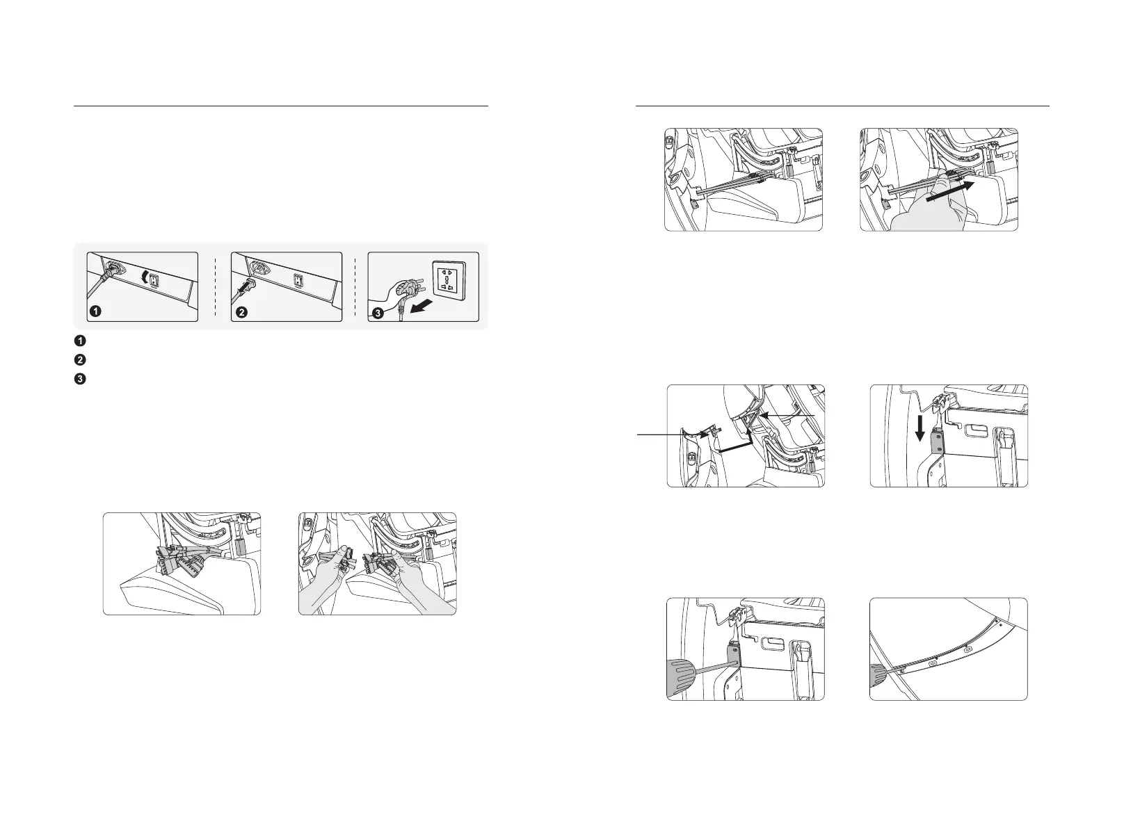
·Cut off the power supply of the whole machine, the figure (schematic diagram of
the whole machine power cut).
Schematic diagram of the whole machine power turning off.
Schematic diagram of unplugging the whole machine wiring.
Schematic diagram of unplugging the power plug.
·Locate the connector plug corresponding to the armrest from the bottom of the
frame and pass it out from the center of the rear end of the frame (Figure 1).
·After passing the connector plug from the middle of the rear end of the frame,
corresponding to each pair of wiring plugs (docking according to the mark on the
physical pair wiring) (Figure 2).
Figure 1
Figure 2
·The connector from the bottom of the frame is inserted firmly with the armrest
connector, and the air pipe connector is also inserted into the position (Figure 3).
·After connecting with the corresponding connecting wires, gently insert the middle
of the steel pipe behind the frame steel frame into the bottom of the frame by
hand, and take care to avoid the air pipe collapse (Figure 4).
Figure 3
Figure 4
·Hold the front and rear ends of the armrests with both hands, first insert the limit
shaft at the rear end of the armrest into the limit shaft card at the lower end of the
back steel frame, then push the armrest up slightly by hand and check whether
the armrest limit shaft is firmly inserted (Figure 5).
·After inserting the rear end of the armrest, hook the front end of the armrest into
the steel tube of the seat frame and press down on the front end of the armrest;
then gently shake the armrest to check whether the front and rear ends of the
armrest are in place (Figure 6).
Figure 5
Figure 6
Limit block
Limit axis
·Aim at the mounting hole of the steel frame on the front end of the fixed handrail,
and fix the handrail and the steel pipe of the holder firmly with two (M5X16)
screws (figure 7).
· fiveTighten the rear end of the armrest and the capsule with M4x10 screws.
Figure 7
Figure 8
2726