5 Calf in stall ation、
Method of usage Method of usage
·Insert the hook on the lower part of the shoulder decoration bar into the groove
below the armrest, then fasten the two metal fasteners in the middle to the
armrest (figure 9).
· Tighten the handrail and decorative bar firmly on the inside shoulder of the
handrail with a screw of ST4.2x12, and then gently shake the entire handrail to
check whether the front and rear ends of the handrail are installed in place. After
the armrest is installed, the installation steps of both armrest are the same (figure
10).
Figure 9
Figure 10
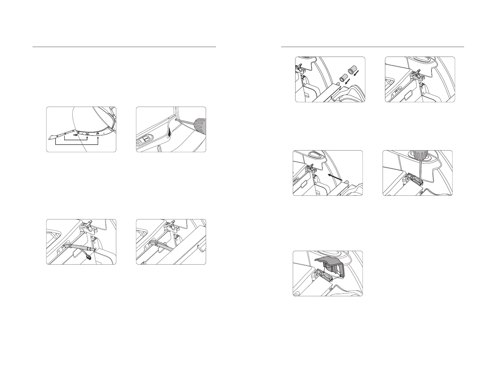
·First cut the connecting wire and the air pipe tie fixed on the steel pipe(figure 1).
·Connect the connecting wire and the air pipe leading from the lower end of the
frame to the lower leg joint, and confirm whether the docking is in place, and then
insert the connecting line and air pipe into the bottom of the seat frame from the
lower end hole of the abutment, and pay attention to avoiding the dead air pipe
when filling(figure 2).
Figure 1
Figure 2
·First insert the rotating inner sleeve and the rotating outer sleeve into the left side
of the calf and the right side of the lower leg (note: the large step must face
inward) (figure 3).
·Then open the calf on the left and right mounts of the massage chair to support the
hinge cover(figure 4).
Figure 3
Figure 4
·Then hang the lower leg (left and right shaft) into the frame support hinge plate at
the same time(figure 5).
·Cover the rotating shaft cover, press the rotating outer sleeve of calf, and then
use a M5x12 pan head Phillips screw to lock the calf support rotating cover, and
the calf is installed(figure 6).
Figure 5
Figure 6
·After the screw is locked, the groove at the back end of the lower leg cover is
clamped onto the pin axis, and then the front end of the lower leg cover is
pressed down completely parallel to the rotating shaft cover plate, and the convex
point at the side of the lower leg cover is stuck into the hole at the side of the
lower leg hook, and the lower leg is installed(figure 7).
Figure 7
29
28