8 QSC Audio Products, Inc.
Bridged mono operation and protection
When the amplifier is operated in bridged mono, its two channels
work in tandem to produce up to twice the voltage swing that a
single channel is capable of. To do this, Channel 2 produces a signal
identical to Channel 1’s, but opposite in polarity—in other words, a
mirror image.
Channel 2’s signal feed (bus BR_MONO_FEED) is an attenuated
version of the signal on Channel 1’s speaker bus. Closing DIP switch
#6 (set to “BRIDGE MONO ON”), connects the BR_MONO_FEED bus
on Channel 1 to the BR_RET bus on Channel 2. The BR_RET bus
drives the non-inverting input of op amp U201:2 directly.
With two channels operating as one, but each having its own
feedback and protection circuitry, it is vital to keep both running as
mirror images. A protection circuit monitors the balance between
Channel 1’s and Channel 2’s signals. Resistors R22 and R23 (R22A,
R22B, R23A, and R23B on the RMX 2450) are equal in value and
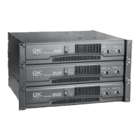
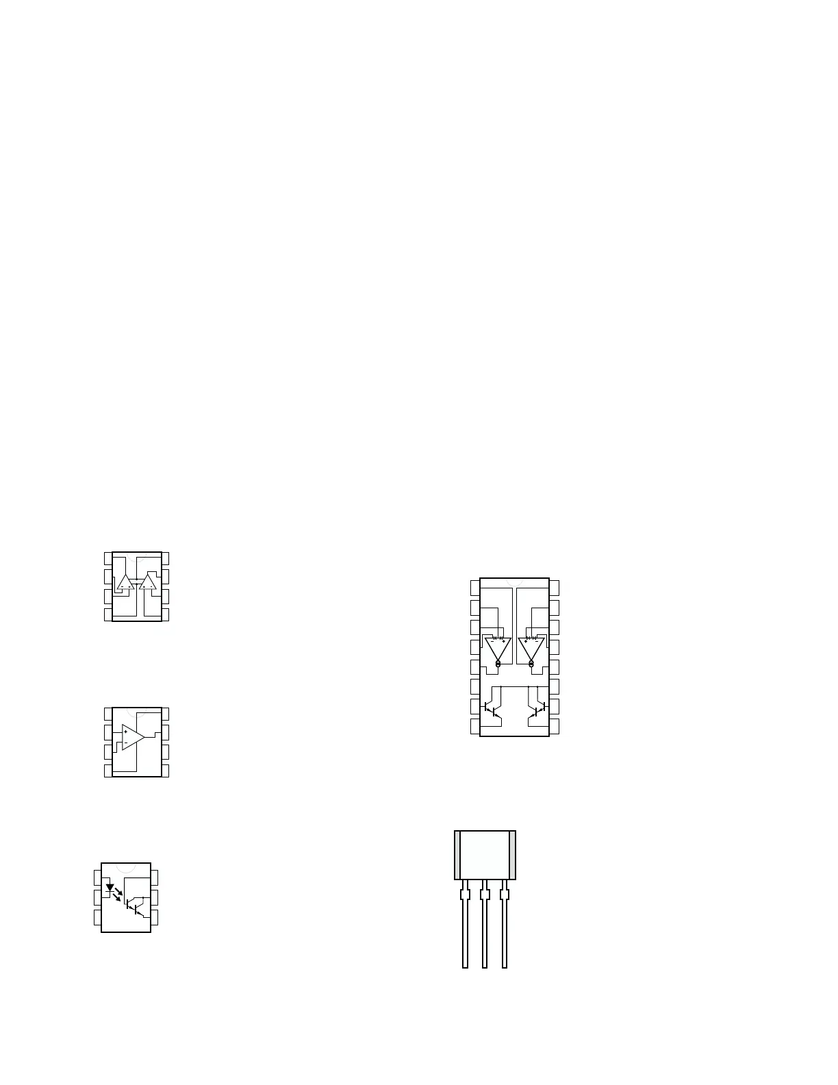
2. Component identification and pinout
1
2
3
4
8
7
6
5
AB
OUTPUT A
INVERTING
INPUT A
NON-INVERTING
INPUT A
V-
OUTPUT B
INVERTING
INPUT B
NON-INVERTING
INPUT B
V+
1
2
3
4
8
7
6
5
GROUND 1
NON-INVERTING
INPUT
INVERTING
INPUT
V-
OUTPUT
BALANCE/
STROBE
BALANCE
V+
1
2
3
4
5
6
7
8
16
15
14
13
12
11
10
9
AB
NON-INVERTING
INPUT A
V-
AMP BIAS INPUT B
NON-INVERTING
INPUT B
INVERTING INPUT B
OUTPUT B
BUFFER INPUT B
BUFFER OUTPUT B
V+
DIODE BIAS B
AMP BIAS INPUT A
DIODE BIAS A
INVERTING INPUT A
OUTPUT A
BUFFER INPUT A
BUFFER OUTPUT A
NE5532AN Dual operational amplifier
LM311 Voltage comparator
LM13600 Dual operational transconductance
amplifier
form a voltage divider between the two channel outputs. If the
output signals are mirror images, the voltage at the junction of the
resistors (bus BR_BAL) will be zero. If the signals are not mirror
images—for example, one channel is defunct, distorting, or reduced
in gain—a voltage will appear on BR_BAL. Through DIP switch 7,
the BR_BAL bus becomes bus BR_CUT and feeds the bases of
transistors Q8 and Q6, which are part of a 4-transistor circuit across
the +15V and -15V rails that supply the op amps and the input
circuitry. If the voltage on BR_CUT goes positive enough to forward-
bias Q8, the transistor’s collector will collapse the +15V rail. At the
same time, the emitter current from Q8 will flow through R25 and
into the emitter of Q7, forward-biasing it, too. The collector of Q7
will then collapse the -15V rail.
Similarly, if BR_BAL goes sufficiently negative, it will forward-bias
Q6, in turn forward-biasing Q9, and these will collapse the ±15V rails.
With the rails collapsed, the op amp and the input circuitry will not
function, which will mute the audio.
4N29 Opto-isolator
1
2
3
6
5
4
2N5064 Sensitive gate thyristor
KAG