6 Securing cutter frame (see fig.10)
Carry the frame to the cutting shop. Set the frame to a desired operating height with the
adjusting screw (21). Lock the position with the nuts (21-1) attaching the table legs (4) to
the underside of the table (3) with screws.
Turn and lower the table support screws (4-1) till they come into contact with the sole
plates (22).
Lock the screws (4-1) with the nuts
(Caution)
If the table support screws are turned down excessively, the cutting table and the cutter
frame are raised. Do not turn the screws
excessively.
【
C
】
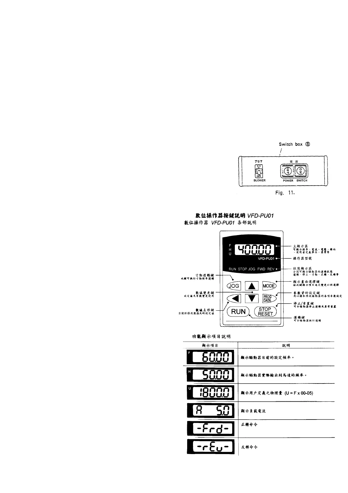
SWITCH FUNCTIONS
7. Switch box (see fig.11.)
Power supply switch: turns on and off the entire
power supply of the band knife cutter.
Blower switch: Turns on and off
the blower.
8. Control panel (see fig.12.)
Speed indicator: Indicates knife
speed. (Unit: m/min) The display
lights up indicating knife speed
during the running of the knife,
and flashes during at rest.
Up/down key: Change knife
speed. Continue to press for
changing speed at a high rate.
Speed can be changed regardless
of whether the knife is running or
at rest.
Start key: Starts up the knife.
Stop key: Stop the knife.
(Caution)
To stop the knife: must use the
stop key on the control panel (9).
If the knife is stopped when
power off, push button on the
switch box (8). Failure of the
inverter may be caused.
 Loading...