6
. Grind distal end accurately to expose spacer screw heads (B).
Warning: Do not grind any deeper.
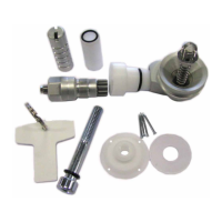
. Remove spacer screws (B) and attach Lock Body with four long
Countersunk Screws. Use medium strength threadlocker and torque
to Nm.
Note: Push Button may be shortened by unscrewing from Lock Body and
cutting it with hacksaw.
Thermoplastic Instructions
. Flatten distal end of Plaster Cast enough to centrally attach Delrin
Tooling Body. Attach with nails provided or double-sided tape
maintaining original pin alignment.
. A small hole may be drilled from edge of Delrin Tooling Body (D)
through length of Plaster Cast to assure maximum vacuum.
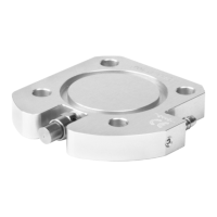
. Attach Lam/Therm Ring to Delrin Tooling Body with Delrin Screw.
Note: Ensure that arrow (A) on Lam/Therm Ring is aligned in AP or
ML direction.
. Vacuum form thermoplastic. Ensure proper forming, especially at
distal end. Thermoplastic must be at least mm thick at distal end.
. Rough-cut and grind plastic in the transverse plane, stopping at spacer
screws (B). Warning: Do not grind any deeper.
. Remove spacer screws (B) and attach Lock Body with four long
Countersunk Screws. Use medium strength threadlocker and torque
to Nm.
Note: Push Button may be shortened by cutting it with hacksaw.
Warning: If Clutch Mechanism is removed during lifetime of lock, torque
to Nm.
 Loading...