Setup
Assemble the Handle
1. Loosen the bolt (Item 64) on the handle socket (60). NOTE: Item numbers refer to the parts list on page 1.
2. Insert the handle.
3. Tighten the bolt.
Air Bleed
Air can accumulate within a hydraulic system during shipment or after prolonged use. This trapped air causes
the jack to respond slowly or feel "spongy." To remove the air, follow the instructions for both the manual pump
and the air pump:
Manual Pump
1. Open the release valve by turning the release knob counterclockwise.
2. Pump the jack handle six full strokes.
3. Close the release valve by turning the release knob clockwise.
4. If the jack does not immediately respond to pumping the handle,
repeat Steps 1–3.
Air Pump
1. Place the jack on a level surface.
2. Open the release valve by turning the release knob counterclockwise.
3. Run the air pump for 20 seconds, then close the release valve by
turning the release knob clockwise.
4. Pump the jack pedal (Item 61) until the jack reaches its maximum
height.
5. Depress the air valve while turning the release knob two full turns
counterclockwise. Continue to depress the air valve until the lift arm fully lowers. Turn the knob clockwise
until it stops. Pump normally.
6. If the jack does not immediately respond to the air pump, repeat steps 1–5, or follow the priming instructions.
Priming the Air Pump
If air cannot be bled using the air pump air bleed procedure, the air pump has lost its prime. To prime the pump:
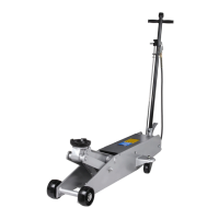
1. Remove the cover board (Item 26).
2. Loosen the bolt (Item 46; also see Figure 1) one-half turn.
3. Close the release valve by turning the release knob clockwise.
4. Run the air pump while repeatedly tightening and loosening the
bolt. (A small amount of oil may seep from underneath the bolt
during this process.)
5. When the piston begins to rise, tighten the bolt.
6. Verify the jack will rise to its full height; add oil to the reservoir
if necessary.
Operating Instructions
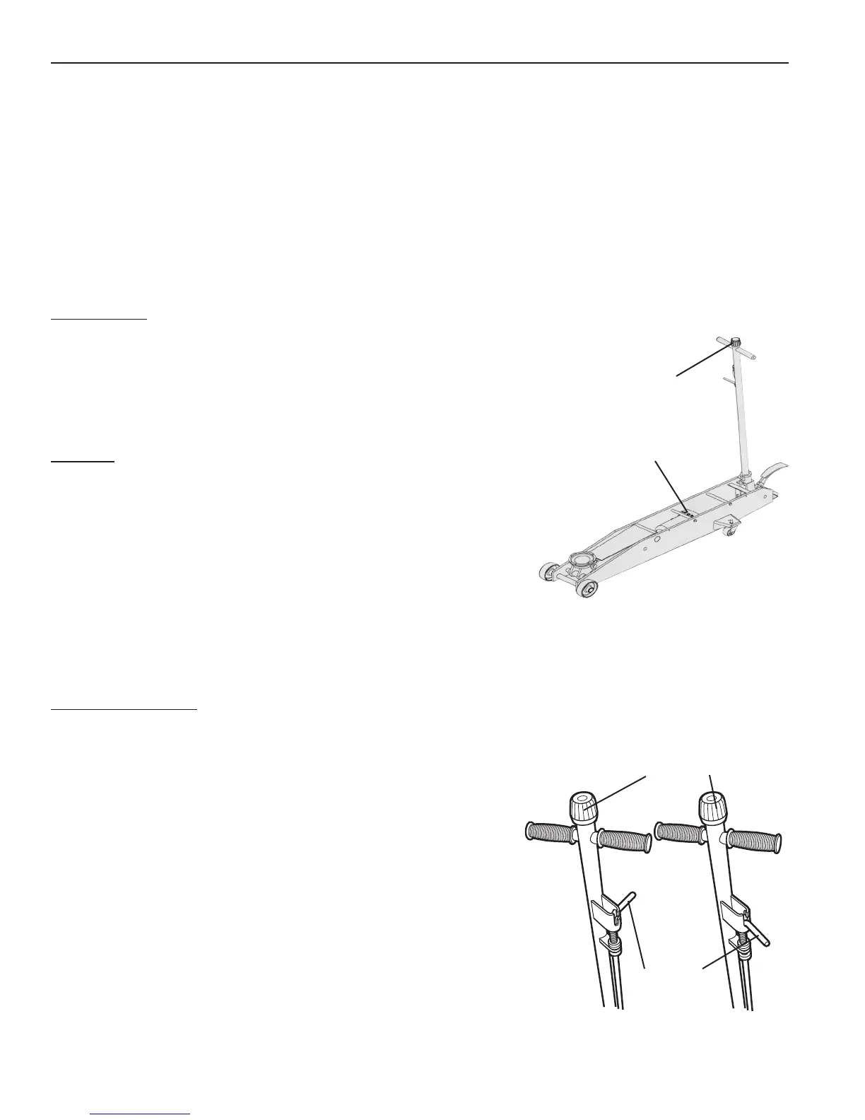
Control rod in Position A: Allows you to pump the jack using the
handle.
Control rod in Position B: Locks the handle in place in three
different positions.
Parts List & Operating Instructions Form No. 565786, Sheet 2 of 3, Back
Control Rod
Release Knob
Figure 2
Position A Position B
Release
Knob
Figure 1
Bolt
 Loading...