Sheet No.
Issue Date: Rev. F April 29, 2019
© Bosch Automotive Service Solutions Inc.
2 of 3
Assembly & Operating Instructions Form No. 102302
Assembly Instructions
(Item numbers refer to parts list No. 100300)
Note:
•
It is easier to assemble the repair stand if you leave the base on the shipping pallet during assembly.
•
Use an overhead crane or lift when assembling this repair stand; a forklift may be used if other means are
not available.
1. Place the head assembly in an upright position.
2. Place the tool box (Item No. 1) on top of the head assembly.
3. Place the jack (13) on the plate as shown in the parts list. Bolt the jack to the plate using lockwashers and
cap screws (21 and 22) and move the completed assembly forward.
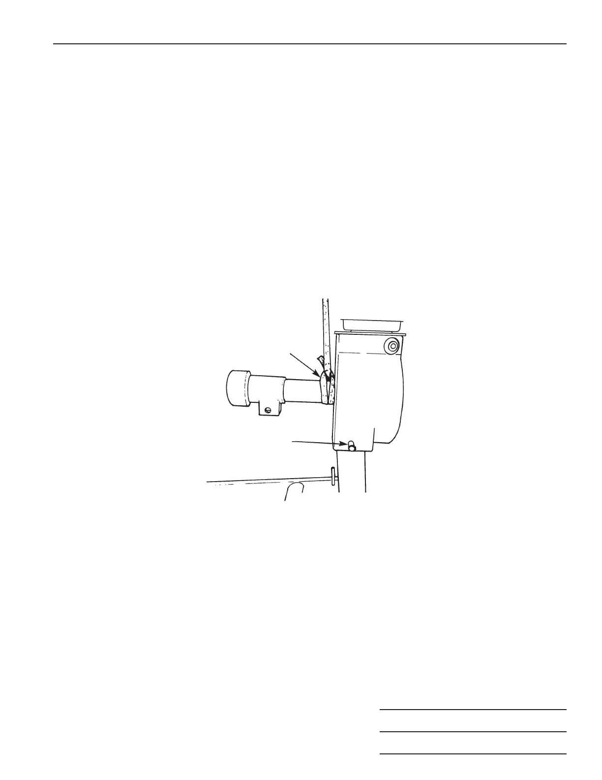
4. Assemble a retaining ring (3) on one end of each pin (Items 11 and 15).
5. Attach a lifting strap around the head assembly as shown in Figure 2. Lift the head assembly and lower it
onto the post. Align the holes and insert the longer pin (11). Place a retaining ring (3) on the other end of
the pin.
6. Raise the lifting jack assembly and fit it into the mounting bracket located under the tilting shaft assembly.
Insert a pin (15) and fasten the pin in place with a retaining ring (3).
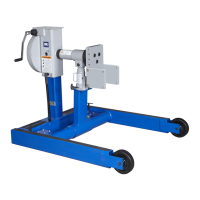
7. Place the jack handle (27) in its storage position on the repair stand as shown in Figure 1.
8. Tighten the collar (5) until snug against the bushing on the tube assembly (2). Back off the collar 1/8 turn
and tighten the set screw (4).
9. If an engine mounting adapter has been included, attach it to the tilting shaft as shown in Figure 1. Torque
the bolts to 610 N•m (450 ft. lbs.)
Note: Use the hex stock (provided) as an adapter with a socket wrench on the allen head screws.
Lifting Strap
Location
Pin
Figure 2