Using the Universal Adapter Plate to Mount an Engine
Figure 3
1. Verify the handle locking mechanism on the engine
stand is engaged before mounting an engine. Refer
to Figure 5.
2.
Select an engine adapter plate that has the correct
bolt pattern for the engine to be serviced. Use the
application chart provided with the adapter plate
to determine which bolt holes adapt to the specific
engine model.
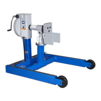
3. Bolt the engine adapter plate to the engine using
the spacers, bolts, and washers specified in the
application chart. Wrench tighten the bolts. See
Figure 3.
4. Attach side plates to the engine adapter plate, but
leave the cap screws and nuts loose.
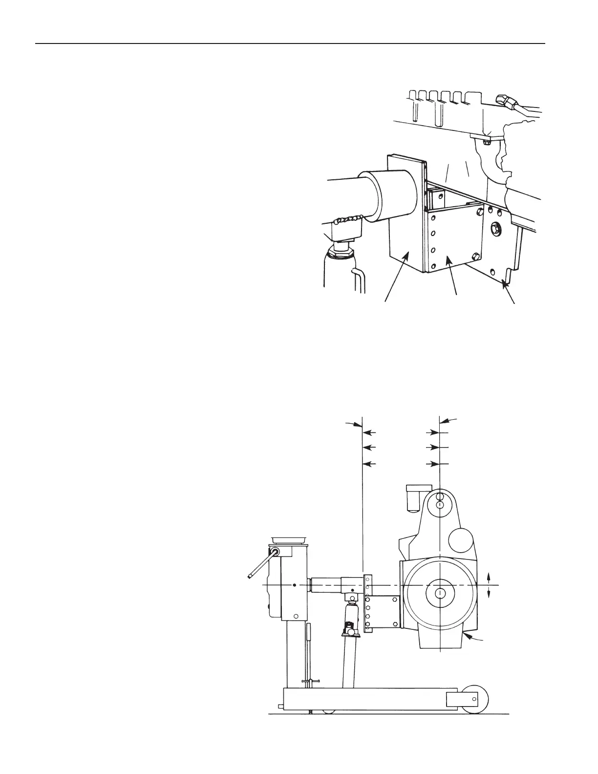
5. See Figure 4. Align the engine (with side plates
attached to the adapter plate) with the universal
adapter plate on the engine stand. Raise or lower
the engine until its center of balance is in-line with
the rotating shaft of the engine stand.
Note: The
engine's center of balance (greatest concentration
of weight) is usually about 50.8 mm (two inches)
above the center of the crankshaft.
Universal
Adapter Plate
Side Plate
Engine
Adapter Plate
Center Line
of Engine
Mounting Hub
Surface
635 mm (25 in.)
508 mm (20 in.)
330 mm (13 in.)
1815 kg (4000 lb.)
2268 kg (5000 lb.)
2722 kg (6000 lb.)
Figure 4
Center
of
Gravity
Within
50.8 mm (2.0 in.)
All Directions
Engine
6. Align the closest tapped holes in the
universal adapter plate with holes in the
side plates. Securely tighten the side
plates to the engine adapter plate on
the engine and to the universal adapter
plate on the engine stand.
Assembly & Operating Instructions Form No. 102302, Sheet 2 of 3, Back