Sheet No.
Issue Date: Rev. F April 29, 2019
© Bosch Automotive Service Solutions Inc.
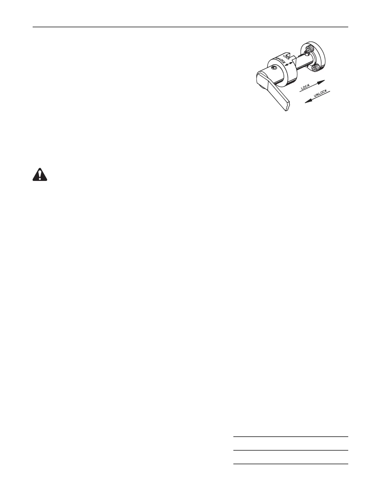
Handle Locking Mechanism
To ensure engine stability in all positions, this repair stand is equipped
with a positive-crank handle locking mechanism. See Figure 5.
To Engage: Slide the collar inward toward the gear housing. Align
and engage the collar slots with the socket head cap screws of the
housing. It may be necessary to rotate the crank slightly to engage the
collar.
To Disengage: Slide the collar away from the housing beyond the
shaft's ball detent.
Figure 5
Assembly & Operating Instructions Form No. 102302
Preventive Maintenance
CAUTION: It is absolutely required that the two grease fittings on the tilting shaft and the gear box
are serviced regularly using a good quality grease. Failure to grease this area can cause equipment
damage and possible injury to the operator.
1. The worm and gear assembly operates in oil contained in the gear cover housing. The oil level should be
just below the fill plug hole located on the lower part of the cover. Check the oil level regularly, and add oil
if necessary (Mobilux, EP-023 or equivalent).
2. Regularly check the oil level in the hydraulic lifting jack. Fully retract the jack piston and remove the small
hex filler plug located on the main body. Add approved hydraulic jack oil until the oil level is just below the
filler plug hole. Install the filler plug.
3. If it is difficult to rotate an engine in one direction only, tighten the collar (Item 5) until snug against the gear
box post. Back off the collar 1/8 turn and tighten the set screw (4).
4. Do not tighten the jack release valve tighter than necessary; never use a pliers on the release valve.
5. Regularly check all cap screws on the engine stand to verify they are still torqued. Refer to parts list No.
100300 for torque specifications.
6. Refer to parts list No. 100300 for repair part numbers.
3 of 3