Page 18 Page 19
900-0093-12-00 Rev C
©2020 OutBack Power. All Rights Reserved.
Common Problems
Symptom Possible Cause Possible Remedy
Current readings are inaccurate or
reversed.
Shunt(s) miswired. Confi rm correct wiring on all shunts.
See page 5.
Current reading is zero with current
confi rmed present.
Shunt not enabled. Enable all shunts that are in use.
See page 7.
Current or SOC readings are
inaccurate.
Unused shunt is still enabled and is picking
up electrical noise.
Disable any shunts not in use.
See page 7.
SOC readings are inaccurate. SOC setting was not set to match
battery capacity.
Unit was not configured and was left
at factory defaults; the factory default
settings may not be accurate for a
given system.
System has not been through a
complete charge cycle recently
.
Multiple partial charge cycles can
introduce errors.
Battery charger settings are not
accurate for the system. Along
with potentially undercharging the
batteries, this can cause the MATE3s
Charge Termination Control to stop
charging at the wrong time.
Charge Factor is set inappropriately
for the batteries.
FN-DC may require calibration.
Ensure the SOC setting matches the
rated capacity of the battery bank.
See page 7.
Follow all programming instructions.
See page 6.
Ensure the SOC setting matches the
rated capacity of the battery bank.
Ensure the full-charge settings
in Battery Setup match both the
charger settings and the battery
manufacturer's requirements.
See page 7.
Complete one or more full charge cycles,
then begin discharging the batteries to
force a reset.
Check all settings and follow all
programming instructions. Set the
charging source according to the
battery manufacturer’
s requirements.
Set Charge Factor according to the
battery manufacturer’s requirements.
See page 7.
See FN-DC Field Calibration.
Aඝච relay is not operating according to the
previous settings.
A
reset to factory defaults may have reset
the relay settings to a 12-volt system.
Set FLEXnet Relay Set Points to the voltage
and other settings appropriate to the system.
See pages 12 and 13.
Battery voltage reading is not accurate. FN-DC may require calibration. See FN-DC Field Calibration.
Troubleshooting
FN-DC Field Calibration
This section outlines the procedure for calibrating a FLEXnet DC Battery Monitor that has already
been installed in a system.
Required Equipment
○ Digital Multi-Meter (DMM)
○ Jeweler screwdriver
○ Previously existing system (MATE3s, HUB, inverter, and/or charge controller)
To Calibrate:
1. Ensure battery bank is fully charged.
2. De-energize system.
3. Remove FN-DC from its mounting location. Maintain all wired connections, including green
communications cable to HUB.
4. Remove FN-DC front cover.
○ Ensure informational sticker is facing up and terminal block is at the far end.
Using the two push tabs, remove the front cover.
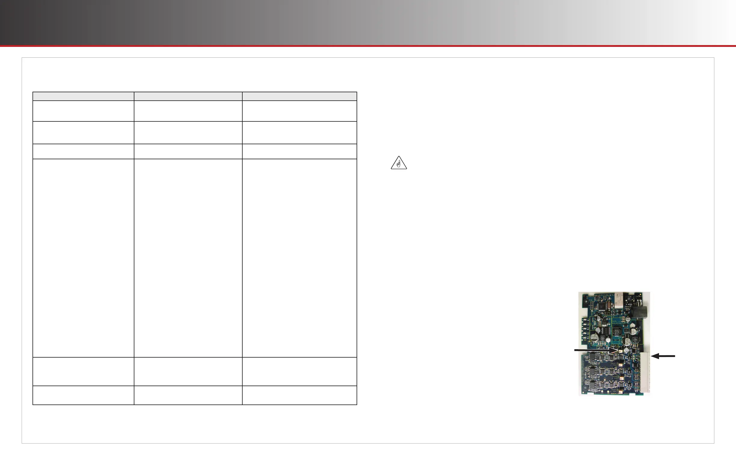
5. Remove red sealant from the R83 trim pot (potentiometer). See fi gure below.
6. Energize system.
7. Measure battery voltage with DMM at terminals 1 and 2
on FN-DC inputs.
8. Read battery voltage from the MATE3s FLEXnet DC
screen. (See page 8.)
9. With a jeweler's screwdriver, adjust the R83 trim pot
until the displayed voltage from the FLEXnet DC screen
matches battery voltage measured with the DMM.
10. Replace front cover.
11. Replace FN-DC in system.
IMPORTANT:
Take all necessary safety precautions when working on energized equipment.
R83
Terminals
1 and 2
 Loading...