Page 4 Page 5
900-0093-12-00 Rev C
©2020 OutBack Power. All Rights Reserved.
CAT5 Cable
Wiring
Block
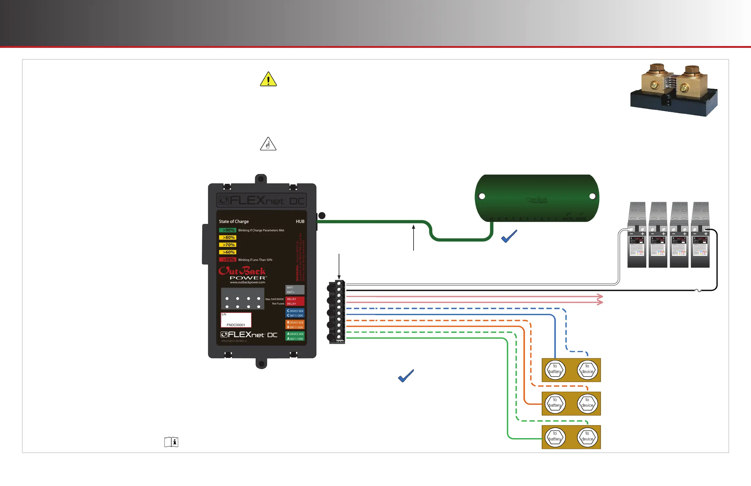
Wiring Connections
Color-coded twisted pair #18 AWG connects the wiring block and
shunt(s) or battery. The wiring must be installed with the proper polarity
to avoid corrupting the data.
○ The wires connected to the wiring block should match the color-coded
label where the wiring block inserts into the FLEXnet DC.
○ The wiring block can accommodate wire sizes from #12 AWG to #26 AWG
(2.5 mm² to 0.20 mm²). Remove ¼" (6 mm) of insulation.
To connect the FN-DC:
1. Connect the white wire from the Bඉග– terminal in the
wiring block to the battery negative terminal; connect
the black wire from the Bඉග+ terminal in the wiring
block to the battery positive terminal.
NOTES:
Although the image shows the Bඉග– and Bඉග+ terminals wired
directly to the battery bank, it is common to wire them to the
positive and negative bus connections in the load center. The
battery readings, however, will be most accurate when wired
directly to the batteries. It is prudent, though not required, to
install a fuse on the positive wire (see CAUTION).
2. Optional: connect relay wires from the Rඍඔඉඡ
terminals in the wiring block to a fan or other powered
accessory that can be triggered using dry contacts (5
A @ 30 Vdc max.). See page 12.
3. Connect the blue / white wire from the wiring block C
Dඍඞඑඋඍ Sඑඌඍ terminal to the terminal of Shunt C that
connects to the device being monitored. Connect the
solid blue wire from the C Bඉග (–) Sඑඌඍ terminal to the
terminal of Shunt C that connects to the battery.
4. Connect the orange / white wire from the wiring block
B Dඍඞඑඋඍ Sඑඌඍ terminal to the terminal of Shunt B that
connects to the device. Connect the solid orange wire
from the B Bඉග (–) Sඑඌඍ terminal to the terminal of
Shunt B that connects to the battery.
5. Connect the green / white wire from the wiring block A
Dඍඞඑඋඍ Sඑඌඍ terminal to the terminal of Shunt A that
connects to the device. Connect the solid green wire
from the A Bඉග (–) Sඑඌඍ terminal to the terminal of
Shunt A that connects to the battery.
6. Tighten all wiring block terminal screws to a torque
value of 4 to 5 in-lb.
7. Connect the CAT5 cable from the FN-DC port labeled
Hඝඊ to the HUB Communications Manager.
Installation Installation
Shunt Operation
The FN-DC uses shunts to measure electrical current. A shunt works by
creating a low-resistance path for current between two points, resulting in
a small voltage drop that can be measured and converted to amperes of
current. The FN-DC can connect to as many as three shunts in order to
monitor current between the battery bank and devices like an inverter or
a charge controller. A typical setup uses one shunt to measure current between the battery bank and an
inverter; a second shunt to measure current fed into the battery bank from a solar array charge controller; and
a third shunt to measure a second charge controller. By tracking the current fl owing into and out of a battery
bank, as well as voltage, the FN-DC can monitor the battery bank’s state of charge (SoC) more accurately
than by simply tracking voltage. See page 14 for a more detailed discussion of SoC.
NOTES
The FLEXnet DC shunts must
be connected to the negative
(low) side of whatever device
they monitor to avoid damaging
the FN-DC.
Shunts must have a 1:10,000
ratio with a maximum current
1000 amps.
1
2
3
4
5
6
IMPORTANT:
Do not run these wires alongside
the battery cables. This can
induce voltage into the wires and
corrupt the data.
Relay wires connect to external
accessory. See page 12 for details.
Shunt C
Shunt B
Shunt A
NOTE
This diagram does not show the MATE3s
system display, which connects to the
HUB product and provides access to FN-DC
data and settings.
Hub
HUB
Communications
Manager
Battery Bank
CAUTION:
Equipment Damage
Do not reverse the white and black
wires (see step 1). This will damage
both the FN-DC and the HUB
Communications Manager. Installing
a fuse on the positive wire (5 A
maximum, 100 Vdc minimum) may
help protect the devices.
Use Port 2 or higher, depending on the requirements
of the configuration and the HUB literature.
 Loading...