24 900-0021-01-00 Rev B
Grounding
The unit must be connected to a grounded, permanent wiring system. If a bond is made
between neutral and ground, make sure only one bond is present in the AC system at any
time. Some codes require the bond to be made at the main panel only. (The GSLC is
equipped with its own bond, which may need to be removed.)
For all installations, the negative battery conductor should be bonded to the grounding
system at only one point. If the OutBack GFDI is present, it can provide the bond. (The
GSLC is also equipped with its own bond, which may need to be removed.)
OutBack products are not designed for use in a positive-grounded system. If it is
necessary to build this system with OutBack products, contact OutBack Technical Support
at
+1.360.618.4363
before proceeding. Additionally, consult the online forum at
www.outbackpower.com/forum/
, where this subject has been discussed extensively.
Table 3 Ground Conductor Size and Torque Requirements
Terminal Location Minimum Conductor Size Torque Requirements
Ground TBB
#8 AWG (0.013 in²) or 10 mm² 25 in-lbs/2.8 Nm
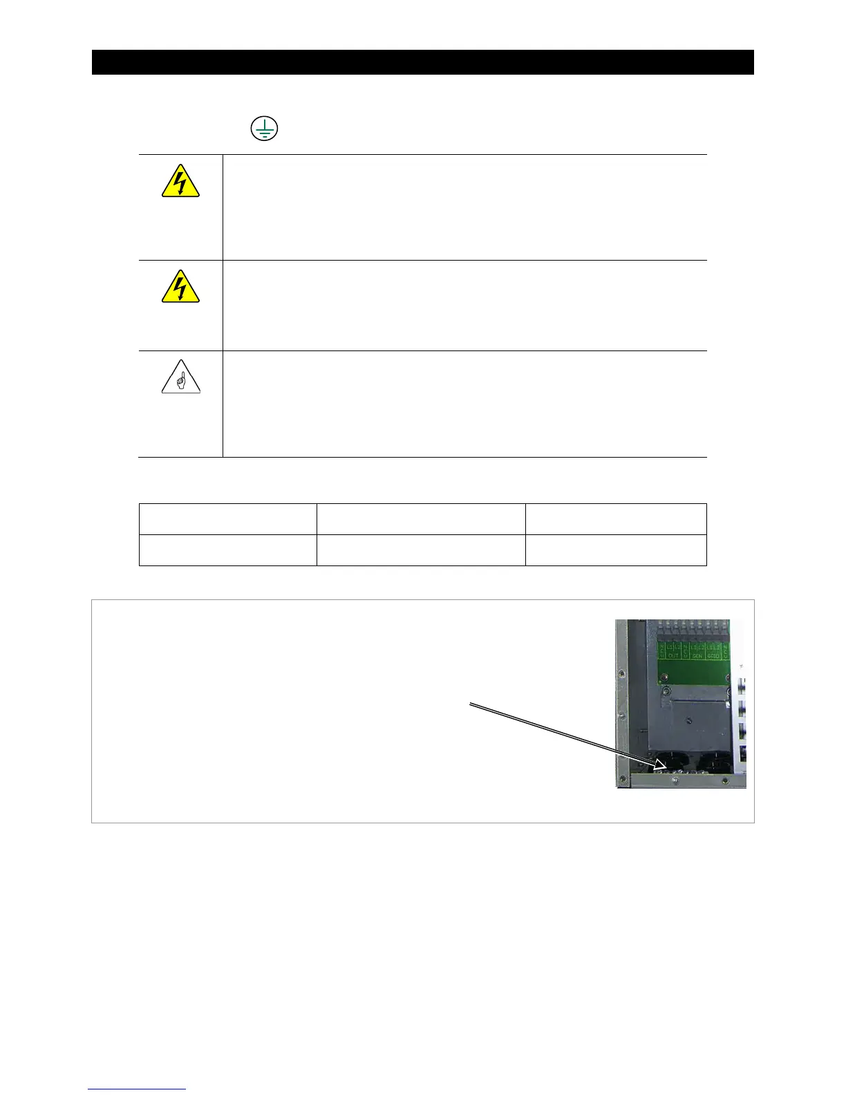
Figure 13 Chassis Ground TBB
The inverter’s ground terminal bus bar (TBB) is used for
making all ground connections to other parts of the
system. Examples include inverter equipment grounding,
generator grounding, load panel grounding, and main
earth ground wire.
This TBB accepts up to #4 AWG (0.033 in²) or 25 mm²wire.