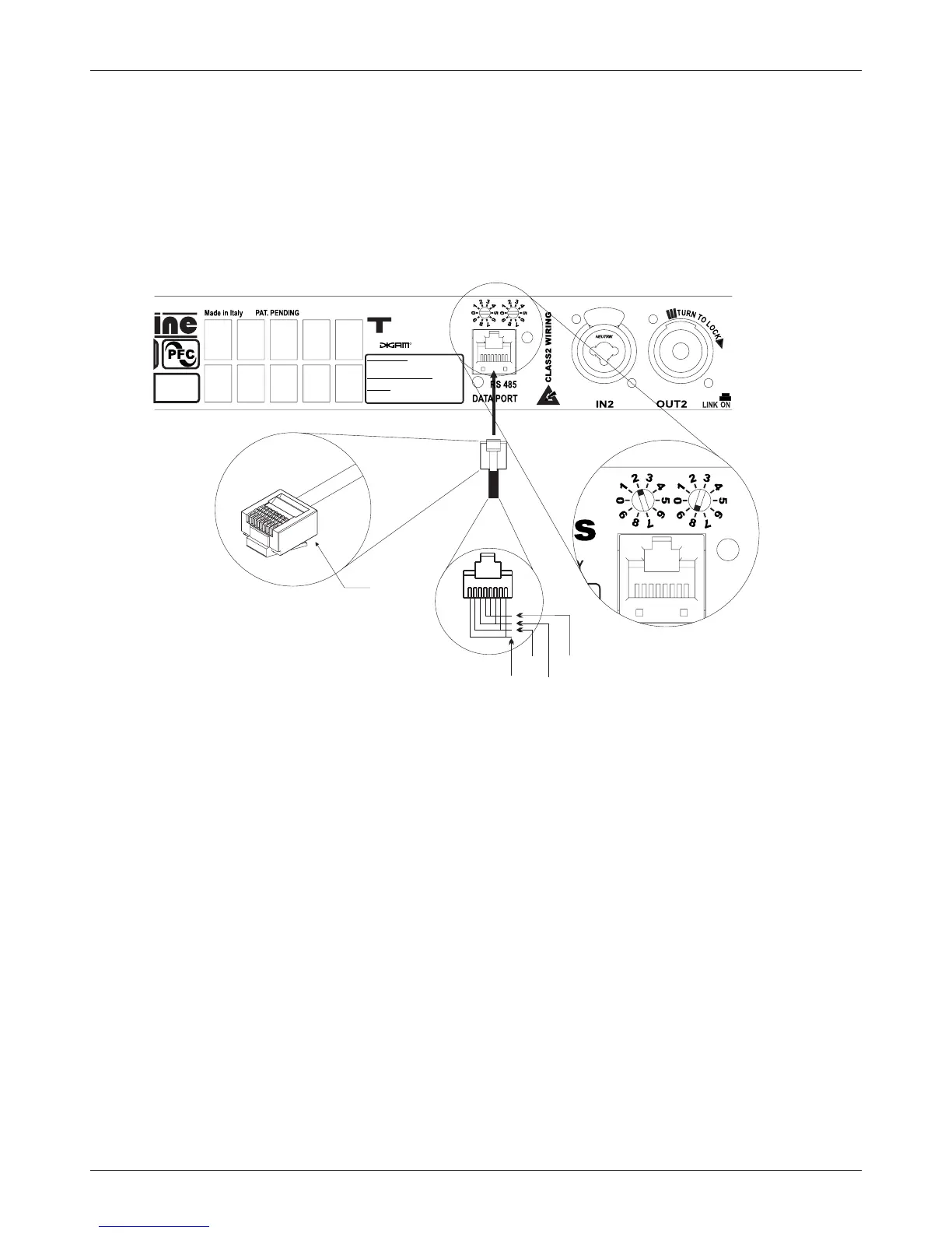
1.7 Connecting Remote Control
You can control the amplifier via a RS48;
connection. The same figure shows also the ID selection for Remote Control (in this case ID=
28); to change the ID, rotate the selectors at the desired value. The selected ID value also is shown in Hardware info
section ( see par 2.3.18 ).
The figure 1.7.1 shows the connection of the data cable to the plug located to the
rear panel of the amplifier.
ID selection example
ID=28
8 pin
modular
plug
(1+ PARALLEL 2+) = POSITIVE
(1- PARALLEL 2- ) = NEGATIVE
OUTPUTS
ANALOG INPUTS
XLR ANALOG : 1=GND 2=IN+ 3=IN-
JACK: SHELL=GND TIP=IN+ RING= IN-
DIGITAL INPUT (OPTIONAL)
XLR AES/EBU : 1=GND 2=IN+ 3=IN-
-Series
TECHNOLOGY
figure 1.7.1
485+
485-
Vext
GND
Pin Layout
Professional amplifiers
T Series
Outline s.r.l. - Via Leonardo da Vinci, 56 - 25020 Flero (Brescia) - Italy
Tel. +39-30-3581341 Fax +39-30-3580431 — Web Site: www.outline.it E-Mail: info@outline.it
9