18
exceed this pressure.
Setting the relief valve:
This should be done, if possible, using the liquid
to be pumped.
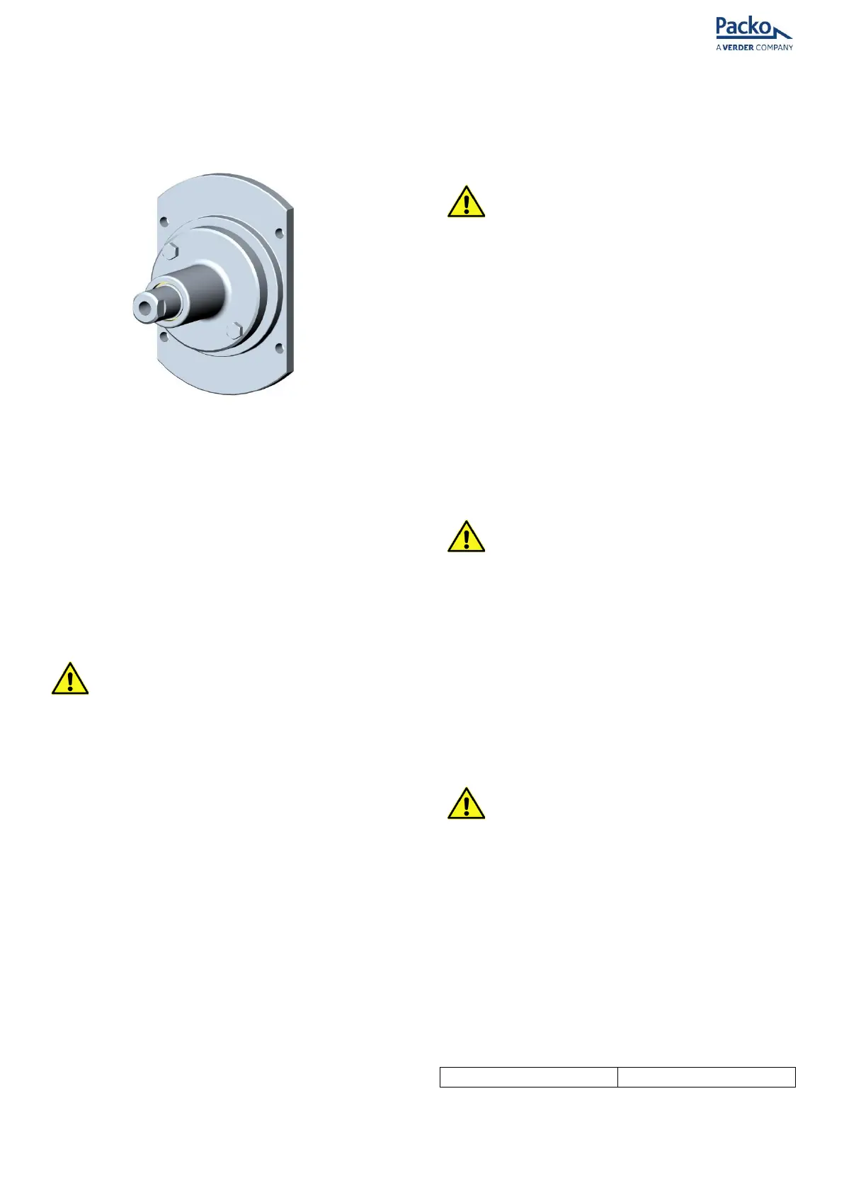
Figure 15 - Relief valve
• Screw the adjusting screw (135) clockwise
so it enters the housing as far as possible.
This ensures that the valve is fully closed.
• A pressure gauge is required to be fitted
in the pipe system directly after the pump.
• Start the pump running.
• Increase the pressure on the pump by
closing a valve downstream or increasing
the pump speed. Continue until the
desired relief valve pressure setting is
achieved.
ATTENTION
• MAKE SURE THAT THE MAXIMUM
PRESSURE OF THE PUMP IS NOT
EXCEEDED. CHECK THE NAMEPLATE.
• Start unscrewing the adjusting screw (135)
counter-clockwise until the pressure
gauge reading starts to drop.
• If a small rod is inserted into the end of
the adjusting screw until it contacts the
end of the valve guide (134) it is possible
to feel the movement of the valve.
The valve is now set.
• Check the relief valve setting by opening
the downstream valve or reducing the
pump speed. It will be necessary to
reduce the pressure to approximately 10%
of the set pressure to ensure full closure
of the relief valve.
• Alternatively stop the pump.
• Re-start the pump or increase the
pressure as stated in relation to the
setting of the relief valve.
• The relief valve should open at the set
pressure.
• Make further adjustments if necessary.
Overload protection
ATTENTION
To prevent injury to personnel or damage to the
pump or system caused by excessive pressures, a
protection device should be fitted such as:
• A pressure switch or sensor that stops the
drive motor. Ideally, the motor should be
fitted with a brake.
• A pressure relief valve or bursting disc
fitted downstream of the pump and
necessary piping to direct excess fluid
away safely.
• A relief Valve fitted to the pump end cover.
• A torque limiting coupling between drive
and pump shaft.
• A motor current sensor.
ATTENTION
Protection devices must be set to operate at, or
below, the safe operating pressure of the pump
or of the system, whichever is the lower.
NOTE; that maximum pressure varies with the
temperature.
3.14 LUBRICATION
Packo HP & LH pumps have oil lubricated shaft
bearings and timing gears.
ATTENTION
Pumps are supplied with Nevastane XSH150 oil in
the bearing housing.
• After the first 120 hours of service, drain
the lubricating oil from the bearing
housing and refill with fresh oil of the
correct grade.
• Check oil level regularly and top up as
necessary.
• Any substantial oil losses should be
investigated immediately.
Oil capacity gearbox: