12
MiniMaster
MA60-16E
ENGLISH
1
4
2
3
5 5
12
9
15
16
18
13
19
7
6
8
11
9
10
10
A
B
C
17
14
T
h
is
d
o
c
u
m
e
n
t
a
n
d
it
s
c
o
n
t
e
n
t
s
a
r
e
t
h
e
e
x
c
lu
s
iv
e
p
r
o
p
e
r
t
y
o
f
P
a
h
lé
n
s
a
n
d
m
a
y
n
o
t
b
e
c
o
p
ie
d
,
r
e
p
r
o
d
u
c
e
d
,
t
r
a
n
s
m
it
t
e
d
o
r
c
o
m
m
u
n
ic
a
t
e
d
t
o
a
t
h
ir
d
p
a
r
t
y
,
o
r
u
s
e
d
f
o
r
a
n
y
p
u
r
p
o
s
e
w
it
h
o
u
t
w
r
it
te
n
p
e
r
m
is
s
io
n
.
Art.no.
Rev.no.
Scale
Designed by: Approved by:
Revised by: Date
Drawn by: Date
Drawing number
Assembly drawing no.
Surface treatment
part of ISO 2768-1
The tolerance class in accordance with this
E
Box 728, SE-194 27 Upplands Väsby, Sweden
Phone +46 8 59411050, Fax +46 8 59086880
4166X0 se tabell
CRO 2010-09-01
ASA 2013-02-19
MiniMaster pH - Redox
MiniMaster pH - fritt klor
M11278 4
5
0
0
31083
310
5
0
0
Sid 3. Till MA60-16
4
3
1
2
1
2
MiniMaster
Pool
MiniMaster
Pool
L2 L1
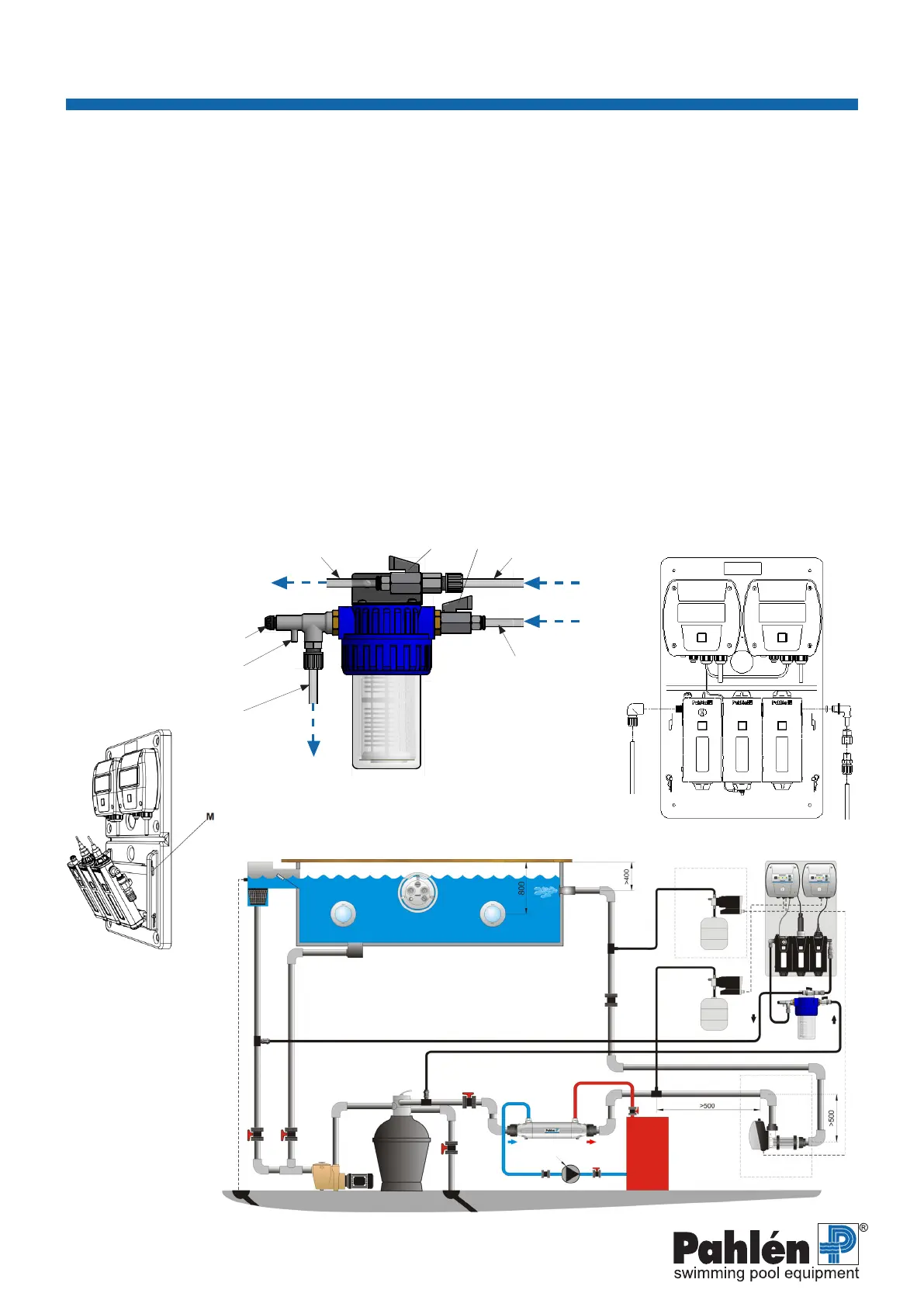
6. Installation
It is recommended that tapping saddles (not included, to be purchased separately) are tted on pipes for measurement water
connection points to and from MiniMaster, and for dosing points for liquid acid and chlorine via hose pumps.
A exible PVC hose (included) must run between the MiniMaster and pre-lter. A rigid PE hose (included) must run between the
pre-lter and the pipes.
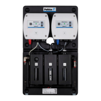
1. Fit the MiniMaster against a wall.
2. Fit the accompanying connections on the Minimaster, see gs. 2 and 3:
Remove the saddle (M), fold the modules forwards, screw the connections tight to the MiniMaster’s inlet and outlet.
3. Assemble the pre-lter, see instruction MA60-22. NB The cover on the lter has an arrow indicating the direction of ow.
4. Fit the pre-lter in a suitable position close to the MiniMaster.
5. Cut the accompanying exible PVC hose to appropriate lengths and connect them, without sharp bends, between the Mini-
Master and pre-lter.
A small piece of exible hose may also be tted to the measurement water outlet if required.
6. Inlet A: Fit a tapping saddle after the sand lter (see A Figure 4) on the pressure side of the pool circulation pump.
7. Outlet B: Fit a tapping saddle after the overow (see B Figure 4) on the suction side of the pool circulation pump.
8. Cut the accompanying rigid PE hose into two appropriate lengths, t hose couplings on both ends.
9. Connect one hose to the pre-lter and inlet A. Use a thread seal when connecting to the tapping saddle/pipe.
10. Connect the other hose to the pre-lter and inlet B. Use a thread seal when connecting to the tapping saddle/pipe.
Alternative location of outlet B: route the hose direct down into the overow (C, Figure 4).
11. If dosing pumps are used for liquid chlorine and acid/alkali, the dosing points must be located at least 500 mm apart,
after other equipment for heating/other disinfection. Chlorine dosing must always be positioned last.
1. Skimmer
2. Main drain
3. Inlet
4. JetSwim
5. Light
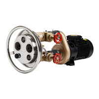
6. Circulation pump pool
(secondary ow)
7. Filter
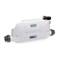
8. Heat exchanger
9. Non-return valve
10. Drain
11.
Circulation pump hot water
(primary ow)
12. Boiler
13. MiniMaster
14. Pre-lter MiniMaster
15. Chlorine dosing
16. Chlorine
17. Acid/alkali dosing
18. Acid/alkali
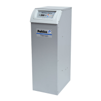
19. Salt chlorinator
Fig. 1. Pre-lter Fig. 2. MiniMaster
Fig. 3.
Fig. 4.
Measurement water cock N
Meassurement water outlet
Pool
MiniMaster
MiniMaster
Pool
PVC hose
PE hose
PVC hose
PE hose
Ball valve L1Ball valve L2
 Loading...