13
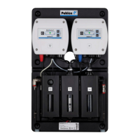
MiniMaster
MA60-16E
ENGLISH
BNC
GND
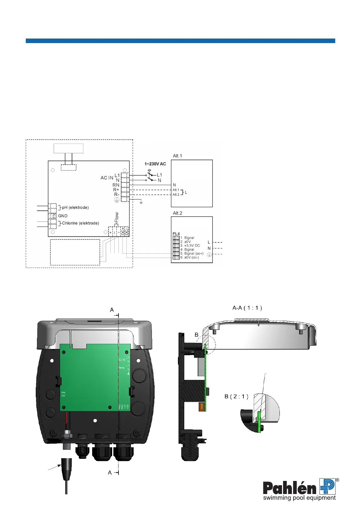
7. Electrical installation
The electrical installation must always be carried out by a qualied electrician.
The pipe installation must be complete before the electrical installation begins.
It is recommended that a power switch is tted before the unit in permanent installations. Interlocked supply voltage from
circulation pump. Connect the power supply cable and any dosing module in accordance with the diagram below.
The multi-pole contacts connected to the circuited board can be removed to allow access to screw terminals for each cable
connection.
AC IN
Main connection of power to unit.
Relay connection
Connection of dosing module, 230VAC,
NOT potential-free.
R+: Phase (for dosing of chlorine and pH
augmenting agent)
R-: Phase (for dosing of pH reducing agent)
RN: Zero/Neutral (Common for dosing)
OC+/OC-:
Transistor ”open collector” output for dosing
module, 5V.
pH/Chlorine:
Contact for connection of electrode.
GND:
Connection of earthing sleeve
(Chlorine measurement only).
The control unit cover can easily be hooked permanently in the open position in order to facilitate installation work.
Undo the cover’s four screws. NB Make sure that the ribbon cable from the circuit board to the cover does not become crushed.
Hook the cover securely as shown in the diagram below.
Fig. 5.
Carefully hook the cover
securely to the edge of the
circuit board.
Display panel
Dosing pump
1~230V AC
Salt chorinator
Red
Black
Red
Black
Brown
Connection of ow
signal between circuit
boards (
416620
only).
Green
White