English
31
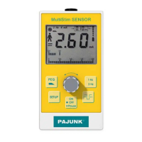
Symbol Meaning
Indication of the battery charge level each of the fi ve segments correspond to 20%
of the battery capacity. This means, if all fi ve segments are visible, then 100% of the
utilizable battery capacity are available, if no segment is visible anymore, then there is
0% battery power available.
Operating modes: PEG (ONLY SENSOR!), cannula or catheter.
Indicates, that setup mode is activated.
Indication of impulse bandwidth. The numerals and units shown within the symbol
render the values selected with the control keys (see description).
3.5 Menu structure setup
SETUP level 1 Adjustment/storage of the volume
Options to choose from: A4, A3, A2, A1 (decreasing volume, beep sounds)
0 (global mute)
1, 2, 3, 4 (increasing volume, pulse sounds)
SETUP level 2 Adjustment/storage of “Cannula – current pulse”
Options to choose from: set value (control device) storage
SETUP level 3 Adjustment/storage of “CATH – current pulse”
Options to choose from: set value (control device) storage
SETUP level 4 Adjustment/storage of “Rp – Threshold”
Options to choose from: 0 – 5 (description see table in chapter Setup Level 4)
SETUP level 5 Adjustment/storage of „PW Selection Mode“
Options to choose from: 0, 1 (description see table in chapter Setup Level 5)
4. Operation
4.1 Pre-operational check
Please observe: Equipment with divergent behavior may not be put into operation. In this case, please
contact the customer service. Electro-medical devices may only be repaired by the manufacturer or by
an institution expressly authorized by the manufacturer.
Please go through the following checking procedure before the initial startup:
1. Press the ON button to start the device. At this moment, the device will automatically start a self-test
sequence. After successful completion of the self-test sequence, the device will switch to the PAUSE
mode. The LCD display will inform you about the current settings. Please replace the battery imme-
diately if there is no indication visible after the device has been switched on. (Observe section Bat-
tery) If the self-test sequence should perhaps have identifi ed a faulty function, then the correspond-
ing error code will be indicated on the LCD. After this occurrence, the device is not operational any
more. (Observe section Error Messages.)
2. Check the electrode cable by visual inspection. Damaged cables may not be used. Attach the elec-
trode cable at the top end of the MultiStim device as follows: position the plug of the electrode
XS190174B MultiStim SWITCH GB.indd 31XS190174B MultiStim SWITCH GB.indd 31 12.03.10 13:5312.03.10 13:53