4
ASSEMBLY (CONTINUED)
MOUNT HEAD ASSEMBLY
Refer to Figure 9.
WARNING:
Although compact, the drill press head assembly is
heavy. Two people are required to mount the drill press head
assembly onto the column.
• Carefully lift the head above the column and slide in onto the
column. Make sure the head slides down over the column as far
as possible. Align the head with the base.
• Using the 5mm hex wrench, tighten the two head lock set
screws (Ref. No. 70) on the right side of the head.
ATTACH BELT TENSION HANDLE
Refer to Figure 8.
• Thread handle (Ref. No. 183) into motor mount plate (Ref.
No. 184).
MOUNT QUILL FEED HANDLE ASSEMBLY
Refer to Figure 8.
• Place key (Ref. No. 146) into feed shaft assembly (Ref. No. 60).
• Place quill feed handle assembly (Ref. No. 147) to the feed shaft
assembly.
• Secure quill feed handle assembly with flat head screw (Ref. No.
150) and a washer (Ref. No. 149).
• Thread handle bar (Ref. No. 151) into quill feed handle assembly.
INSTALL THE CHUCK
Refer to Figure 8.
WARNING: Before any assembly of the chuck and arbor to the drill
press head, clean all mating surfaces with a nonpetroleum based
product, such as acetone or alcohol. Any oil or grease used in the
packing of these parts must be removed otherwise the chuck may
come loose during operation.
• Place the chuck (Ref. No. 131) onto the spindle arbor (Ref. No.
134) while lowering the spindle by turning the feed handles
(Ref. No. 147) counterclockwise, until the slot appears on the
quill.
• Push the chuck and spindle arbor up into the spindle, making
sure the tang is engaged and locked in the inner slot of the
spindle. Once tang is oriented correctly, drill duck will not rotate
without turning the spindle.
• Open the jaws of the chuck (Ref. No. 131) by rotating the chuck
sleeve clockwise. To prevent damage, make sure the jaws are
completely receded into the chuck.
NOTE: Clean the taper with acetone or alcohol cleaner before
inserting it into the arbor.
• Using a rubber mallet, plastic-tipped hammer, or a block of
wood and a hammer, firmly tap the chuck upward into position
on the spindle shaft.
CHUCK KEY STORAGE
Refer to Figure 8 and 9.
• Storage holder (Ref. No. 68) for the chuck key (Ref. No. 132) is
located on the right side of the head.
INSTALLATION
MOUNT DRILL PRESS
• Drill press must be mounted to flat level surface. Use shims or
machine mounts if necessary. Do not mount drill press in direct
sunlight.
• Be sure to bolt drill press to floor or bench securely to prevent
tipping and minimize vibration.
• Tighten all nuts and bolts that may have loosened during
shipment.
ELECTRICAL REQUIREMENTS
The motor is designed for operation on the voltage and frequency
specified. Normal loads will be handled safely on voltages not more
than 10% above or below the specified voltage.
Running the unit on voltages which are not within the range may
cause overheating and motor burn-out. Heavy loads require that
the voltage at motor terminals be no less than the voltage
specified.
GROUNDING INSTRUCTIONS
Refer to Figures 2, 3 and 4.
WARNING: Improper connection of equipment grounding
conductor can result in the risk of electrical shock. Equipment
should be grounded while in use to protect operator from
electrical shock. Check with a qualified electrician if grounding
instructions are not understood or if in doubt as to whether the
tool is properly grounded.
This tool is equipped with an approved 3-conductor cord rated at
300V and a 3-prong grounding type plug for your protection
against shock hazards.
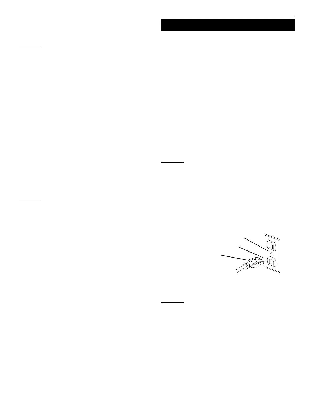
Grounding plug should be plugged directly into a properly installed
and grounded 3- prong grounding-type receptacle, as shown in
Figure 2.
Do not remove or alter grounding prong in any manner. In the
event of a malfunction or breakdown, grounding provides a path of
least resistance for electrical shock.
WARNING:
Do not permit fingers to touch the terminals of plug
when installing or removing from outlet.
Plug must be plugged into matching outlet that is properly
installed and grounded in accordance with all local codes and
ordinances. Do not modify plug provided. If it will not fit in outlet,
have proper outlet installed by a qualified electrician.
Inspect tool cords periodically, and if damaged, have repaired by an
authorized service facility.
Green (or green and yellow) conductor in cord is the grounding
wire. If repair or replacement of the electric cord or plug is
necessary, do not connect the green (or green and yellow) wire to a
live terminal.
Where a 2-prong wall receptacle is encountered, it must be
replaced with a properly grounded 3-prong receptacle installed in
accordance with National Electric Code and local codes and
ordinances.
Figure 2 – 3-Prong receptacle.
Properly Grounded Outlet
Grounding Prong
3-Prong Plug
Palmgren Operating Manual & Parts List 9680157A & 9680158A
 Loading...