l NETWORK CONFIGURATION: High-Pass network, shunt variable
16 μ H inductor, series xed 10 μ H inductor
l DIFFERENTIAL CAPACITOR: 470 pF - 10 pF - 470 pF;
Voltage rating 5.5 kV
l L AND C: Stepper motor-controlled
l FREQUENCY RANGE: 1.8 MHZ to 54 MHZ
l MATCHING RANGE: 8:1
l POWER RANGE: 1800 watts PEP/CW 1.8-29.9 MHZ;
800 watts PEP 50-54 MHZ
l TUNING LEVEL: Minimum level 2 watts,
single tone carrier up to 200 watts
l TUNING ACESS TIME: Typically <10 secs 80m to 6m;
3-5 secs 80m to 160m
l DUTY CYCLE: 100% SSB AND CW
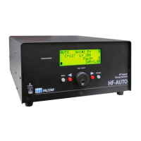
l DIGITAL DISPLAY: RF Power, SWR, Frequency, Antenna
selection, Position of L and C;
Modes: Auto, Manual, Bypass, Setup
l OUTPUT: 3 Output connectors S0-239
l CHASSIS & COVER: 11 ga. .090 gold Iridite Treated Aluminium,
Powder-coated top cover and front panel
l DC POWER: 12 - 13.8 VDC at 4 Amps Peak, 3 Pin
Amphenol Type connector cord supplied
l DIMINSIONS: 12.5” W x 6.75“ H x 14” D
l WEIGHT: 20 LBS, 9 Kg
HF-AUTO SPECIFICATIONS
Page 2 PALSTAR
The HF-AUTO is a matching system that is a complete stand-alone RF
Tuneable Auto T Network tuner.
It is completely independent of data from an external source to
determine frequency of tracking from Band to Band. As a result of this
feature, the HF-AUTO will function with any transmitting device
without interconnecting data cable attachments.
The HF-AUTO uses an RF Coupler that provides voltage and current
information from 1.8 MHZ to 54 MHZ.
This informtion is then processed by a pair of processing devices that
provide accurate phase oriented forward and reected values that are
used in two TI processors to calculate SWR.
This allows for detection of frequency and SWR at very low levels,
typically 2 watts, and is scaled to read these levels up to 1800 watts.
The processors establish the threshold for tuning and uses this
information to see if a tuning sequence is required.
A preset voltage for all the frequencies are used to determine the
positions of the variable dierential capacitor and the roller inductor
by a precise mechanical sprocket and kevlar belt system.
This determines with great accuracy and repeatability the exact
location of L&C needed to execute a tune sequence. This system
samples DC voltage and compares this to the intended frequency band
and sees that if the SWR is more than the preset tuning set by the user
then the steppers for L & C will adjust to that voltage which will
represent the mimimum SWR.
This will be better than 1.2:1, typically 1.05.
THEORY OF OPERATION
 Loading...