EasyManua.ls Logo

Panasonic AG-7500 - Page 7

Panasonic AG-7500
34 pages
Print Icon
To Next Page IconTo Next Page
To Previous Page IconTo Previous Page
Loading...
@
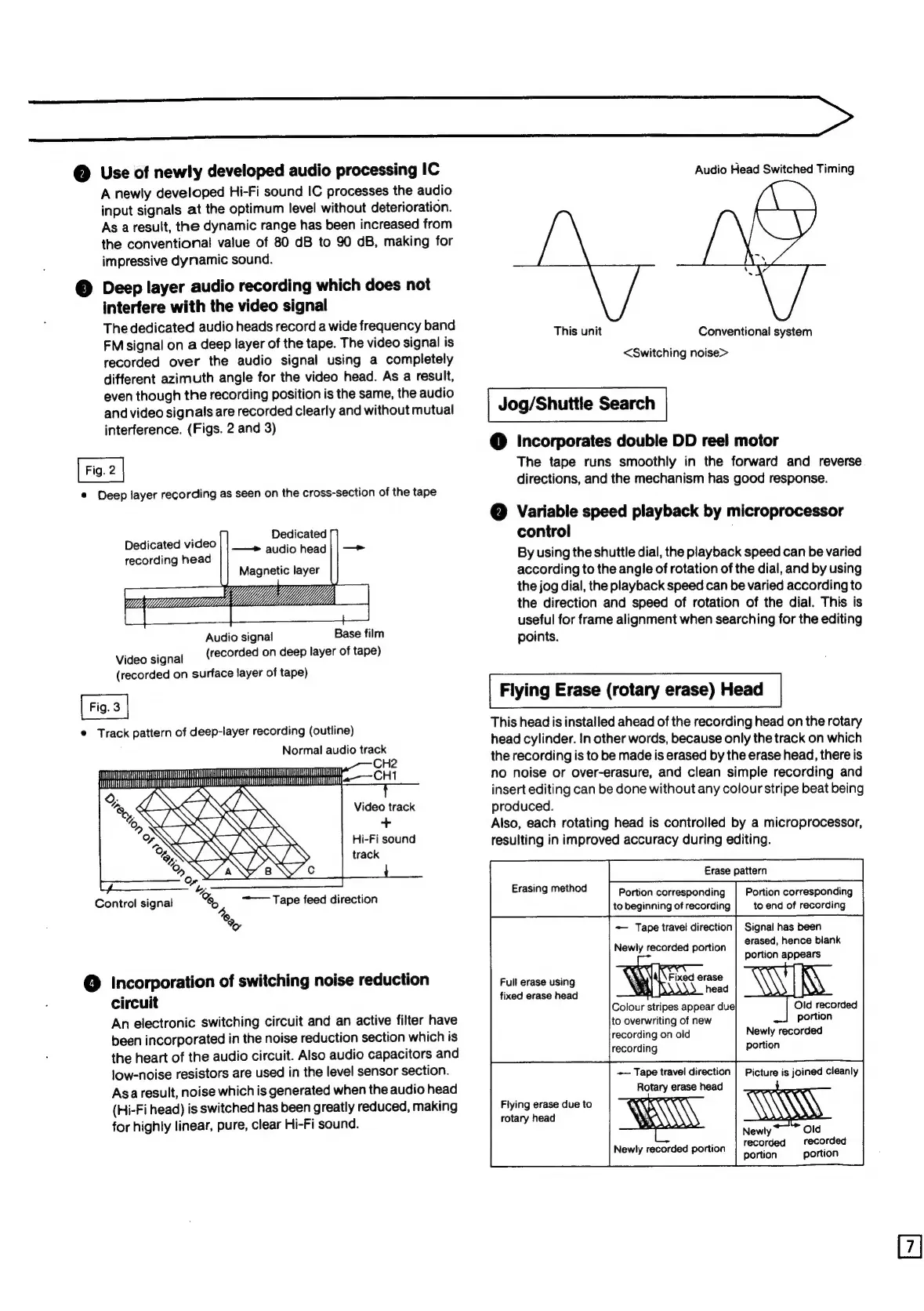
Use
of
newly
developed
audio
processing
IC
A
newly
developed
Hi-Fi
sound
IC
processes
the
audio
input
signals
at
the
optimum
level
without
deterioration.
As
a
result,
the
dynamic
range
has
been
increased
from
the
conventional
value
of
80
dB
to
90
dB,
making
for
impressive
dynamic
sound.
©
Deep
layer
audio
recording
which
does
not
interfere
with
the
video
signal
The
dedicated
audio
heads
record
a
wide
frequency
band
FM
signal
on
a
deep
layer
of
the
tape.
The
video
signal
is
recorded
over
the
audio
signal
using
a
completely
different
azimuth
angle
for
the
video
head.
As
a
result,
even
though
the
recording
position
is
the
same,
the
audio
and
video
signals
are
recorded
clearly
and
without
mutual
interference.
(Figs.
2
and
3)
©
Deep
layer
recording
as
seen
on
the
cross-section
of
the
tape
Dedicated
——
audio
head
Dedicated
video
recording
head
Base
film
Audio
signal
(recorded
on
deep
layer
of
tape)
Video
signal
(recorded
on
surface
layer
of
tape)
©
Track
pattern
of
deep-layer
recording
(outline)
Normal
audio
track
CH2
ae
—
CH1
MMMM
VICHUASUUUUIGUGAUEONLUTGSERHAEUHUDOUUUUUTUUEUUUO
eve
UU
Video
track
+
Hi-Fi
sound
track
@
Incorporation
of
switching
noise
reduction
circuit
An
electronic
switching
circuit
and
an
active
filter
have
been
incorporated
in
the
noise
reduction
section
which
is
the
heart
of
the
audio
circuit.
Also
audio
capacitors
and
low-noise
resistors
are
used
in
the
level
sensor
section.
Asa
result,
noise
which
is
generated
when
the
audio
head
(Hi-Fi
head)
is
switched
has
been
greatly
reduced,
making
for
highly
linear,
pure,
clear
Hi-Fi
sound.
Audio
Head
Switched
Timing
This
unit
Conventional
system
<Switching
noise>
Jog/Shuttle
Search
@
Incorporates
double
DD
reel
motor
The
tape
runs
smoothly
in
the
forward
and
reverse
directions,
and
the
mechanism
has
good
response.
@
Variable
speed
playback
by
microprocessor
control
By
using
the
shuttle
dial,
the
playback
speed
can
be
varied
according
to
the
angle
of
rotation
of
the
dial,
and
by
using
the
jog
dial,
the
playback
speed
can
be
varied
according
to
the
direction
and
speed
of
rotation
of
the
dial.
This
is
useful
for
frame
alignment
when
searching
for
the
editing
points.
Flying
Erase
(rotary
erase)
Head
This
head
is
installed
ahead
of
the
recording
head
on
the
rotary
head
cylinder.
In
other
words,
because
only
the
track
on
which
the
recording
is
to
be
made
is
erased
by
the
erase
head,
there
is
no
noise
or
over-erasure,
and
clean
simple
recording
and
insert
editing
can
be
done
without
any
colour
stripe
beat
being
produced.
Also,
each
rotating
head
is
controlled
by
a
microprocessor,
resulting
in
improved
accuracy
during
editing.
Portion
corresponding
Portion
corresponding
to
beginning
of
recording
to
end
of
recording
—
Tape
travel
direction|
Signal
has
been
erased,
hence
blank
portion
appears
Old
recorded
portion
Newly
recorded
portion
Erasing
method
Newly
recorded
portion
Full
erase
using
fixed
erase
head
Colour
strip
to
overwriting
of
new
recording
on
old
——
Tape
travel
direction
Rotary
erase
head
Picture
is
joined
cleanly
Flying
erase
due
to
rotary
head
Newly
recorded
recorded
portion
portion
Newly
recorded
portion