EasyManua.ls Logo

Panasonic CQ-C1110GN User Manual

Panasonic CQ-C1110GN
32 pages
To Next Page IconTo Next Page
Page #1 background imageLoading...
Page #1 background image
General
Power Supply 12V DC(11V-16V),
Test Voltage 14.4V
Negative Ground
Tone Control (Bass) ±12dB at 100Hz
Tone Control (Treble) ±12dB at 10Hz
Current Consumption Less than 2.5A
(CD mode; 0.5W × 4-speaker)
Maximum Power Output 45W × 4 (at 4)
Power Output 20W × 4 (DIN45 324, at 4)
Speaker Impedance 4-8
Pre-amp Output Voltage 2.5V (CD mode)
Pre-amp Output Impedance 200
CD Player
Sampling Frequency 8 Times Oversampling
Pick-up Type Astigma 3-Beam
Light Source Semiconductor Laser
Wave Length 780 nm
Frequency Response 20 Hz-20kHz (±1dB)
Signal to Noise Ratio 96dB
Total Harmonic Distortion 0.01% (1kHz)
Wow and Flutter Below Measurable Limits
Channel Separation 75dB
© 2004 Matsushita Electric Industrial Co., Ltd. All
rights reserved. Unauthorized copying and
distribution is a violation of law.
CQ-C1120AN
CQ-C1120GN
CQ-C1110AN
CQ-C1110GN
CQ-C1100VN
CD Player/Receiver
Radio
FM
Frequency Range 87.5MHz - 108MHz
Usable Sensitivity 6dB/µV(S/N 30dB)
Stereo Separation 35dB (at 1kHz)
MW
Frequency Range 531kHz - 1,602kHz
Usable Sensitivity 28dB/µV (S/N 20dB)
LW
Frequency Range 153kHz - 279kHz
Usable Sensitivity 32dB/µV (S/N 20dB)
Dimensions (W×H×D)** 178×50×155mm
Weight** 1.4 kg
* Specifications and the design are subject to possible modification
without notice due to improvements.
** Dimensions and Weight shown are approximate.
** Above specifications comply with EIA standards.
AUTOMOTIVE AFTERMARKET
Specifications*
ORDER NO. ACED040125C8

Other manuals for Panasonic CQ-C1110GN

Question and Answer IconNeed help?

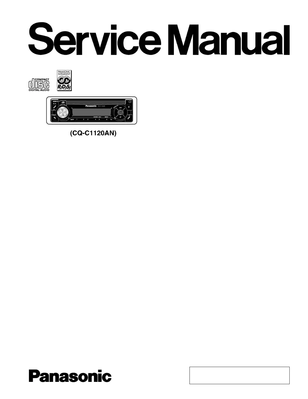
Do you have a question about the Panasonic CQ-C1110GN and is the answer not in the manual?

Panasonic CQ-C1110GN Specifications

General IconGeneral
BrandPanasonic
ModelCQ-C1110GN
CategoryCar Receiver
LanguageEnglish

Summary

Specifications

General

General technical specifications for the device.

Radio

Radio frequency range and sensitivity specifications.

CD Player

CD player technical specifications, including sampling frequency and light source.

WARNING

IMPORTANT SAFETY NOTICE

ABOUT LEAD FREE SOLDER (PbF)

FEATURES

MAINTENANCE

LASER PRODUCTS

WIRING CONNECTION

BLOCK DIAGRAM

Main/Display Block

Block diagram of the main and display sections of the unit.

BLOCK DIAGRAM

CD Servo Block

Block diagram illustrating the CD servo control system.

TERMINALS DESCRIPTION

Main Block

Detailed pin descriptions for the main IC (IC601).

Display Block

Detailed pin descriptions for the display IC (IC901).

TERMINALS DESCRIPTION

CD Servo Block

Detailed pin descriptions for the CD servo IC (IC1).

PACKAGE AND IC BLOCK DIAGRAM

Main Block

Package and block diagram for the main control ICs.

PACKAGE AND IC BLOCK DIAGRAM

CD Servo Block

Package and block diagram for CD servo control ICs.

REPLACEMENT PARTS LIST

EXPLODED VIEW (Unit)

CD PLAYER MECHANISM PART

EXPLODED VIEW (CD Deck)

WIRING DIAGRAM

Display Block

Wiring diagram for the display circuit board.

WIRING DIAGRAM

Main Block (Top View)

Top view wiring diagram of the main circuit board.

WIRING DIAGRAM

Main Block (Bottom View)

Bottom view wiring diagram of the main circuit board.

WIRING DIAGRAM

CD Servo Block

Wiring diagram for the CD servo circuit board.

SCHEMATIC DIAGRAM-1

Display Block

Schematic diagram for the display block, showing component connections.

SCHEMATIC DIAGRAM-2

Main Block

Schematic diagram for the main block, detailing circuit connections.

SCHEMATIC DIAGRAM-2

CD Servo Block

Schematic diagram for the CD servo block, illustrating circuit layout.

Related product manuals