Do you have a question about the Panasonic CQ-C1110AN and is the answer not in the manual?
Details power supply, tone control, current consumption, output power, speaker impedance, and pre-amp output.
Covers FM, MW, and LW frequency ranges and usable sensitivity.
Lists sampling frequency, pick-up type, light source, wave length, frequency response, S/N ratio, THD, and channel separation.
Service is for experienced technicians; misuse can cause serious injury or death.
Highlights critical safety parts (marked with A) requiring manufacturer's specified replacements.
Covers product features, fuse, maintenance, laser safety, and lead-free solder information.
Includes unit dimensions and specific technical notes for radio and CD deck blocks.
Diagram showing power connector, speaker connection, and pre-out rear connections.
Illustrates connections between Main P.C.B, Display P.C.B, and CD Servo P.C.B.
Schematic showing the interconnection of components in the main and display sections.
Diagram illustrating the optical pick-up, RF AMP, CD DSP, and CD servo control circuits.
Detailed pin descriptions for IC601 (Main Block) including I/O and voltage.
Detailed pin descriptions for IC901 (Display Block) including I/O and voltage.
Pin descriptions for CD Servo IC1 and IC4, detailing signals, I/O, and voltage.
Block diagram for IC201 (Mixer/Amplifier) and IC401 (Data Shift Register/Latch).
Block diagram for IC701 (Power Supply) and IC702 (Level Detector).
Block diagrams for IC271 (Power Amplifier) and IC901 (Oscillator/PLL).
Block diagram for IC4 (Coil/Motor Drive), illustrating level shifts and signal paths.
List of ICs and transistors with part numbers, descriptions, and remarks.
Lists diodes and capacitors with part numbers, descriptions, and remarks.
Lists diodes and resistors with part numbers, descriptions, and remarks.
Lists capacitors, connectors, coils, crystals, lamp, and varistor with part numbers and descriptions.
Lists diodes specific to the display block with part numbers and remarks.
Lists switches, LCD, ICs, transistors, and diodes with part numbers and remarks.
Lists capacitors used in the CD servo section with part numbers and descriptions.
Lists resistors and connectors with part numbers and descriptions.
Lists coils, crystals, accessories, installation, and mechanical parts with references.
Lists unit components by reference number, part number, description, and remarks.
Visual diagram showing the assembly and placement of major unit components.
Lists miscellaneous CD player mechanism parts like frame, covers, dampers, and chassis rivets.
Lists mechanical components such as spindle motor, gears, levers, springs, and optical pick-up.
Diagram illustrating the assembly and placement of CD deck mechanism components.
Shows the wiring layout for the display PCB from top and bottom perspectives.
Illustrates the wiring and component placement on the main PCB's top side.
Illustrates the wiring and component placement on the main PCB's bottom side.
Shows the wiring and component layout for the CD servo PCB.
Detailed schematic of the display block, showing ICs, connections, and signal flow.
Schematic detailing the main block, including power supply, system control, and audio circuits.
Detailed schematic of the CD servo block, showing optical pick-up, motor drives, and servo control.
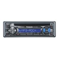
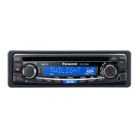
| Type | Car Receiver |
|---|---|
| Max Power Output | 50W x 4 |
| CD Playback | Yes |
| MP3 Playback | Yes |
| USB Port | No |
| Bluetooth | No |
| Display Type | LCD |
| Tuner Bands | FM/AM |
| Channels | 4 |
| WMA Playback | No |
| AAC Playback | No |
| Remote Control | Yes |
| Tuner | FM/AM |
| AUX Input | Yes |
| Preamp Outputs | 1 Pair (Rear) |





 Loading...