10.1. Main Block
IC601 : C2CBHF000322
Pin
No.
Port Description I/O (V)
FM AM CD
1 NC (Ground pull down) I 0 0 0
2 NC (Ground pull down) I 0 0 0
3 NC (Ground pull down) I 0 0 0
4 AVSS Ground - 0 0 0
5 AF_MUTE AF mute O/I 5 5 5.1
6 AMP_CNT Amp control O 5 5 5.1
7 AVREF1 (Conecting to +5V) - 5 5 5.1
8 CD_S0 CD data I 0 0 0
9 CD_SI CD data O 0 0 2.8
10 CD_SCK CD clock O 0 0 5
11 CDC_DATA(NC) No connection - - - -
12 BATT BATT detection I 5 5 5
13 CDC_CLK(NC) No connection - - - -
14 REW_OUT(NC) No connection - - - -
15 BZ_OUT Buzzer signal output O 0 0 0
16 PLL_D0 PLL data I 5.1 5.1 5.1
17 PLL_DI PLL data O 0 0 0
18 PLL_CLK PLL clock O 5 5 5.1
19 PLL_CE PLL chip enable O 0 0 0
20 NC No connection - - - -
21 NC No connection - - - -
22 MUTE Mute control output O 5 5 5.1
23 NC No connection - - - -
24 CD_STB CD strobe - 0 0 5
25 CD_AO CD AO - 0 0 4.4
26 CD_RST(NC) No connection - - - -
27 CD_RFOK CD RFOK I 0 0 4.9
28 CD_LOCK CD lock I 0.5 0.3 4.9
29 CD_LIMIT CD limit I 0 0 5
30 CD_SW2 CD SW2 I 5 5 0
31 NC No connection - - - -
32 NC No connection - - - -
33 VSS1 Ground - 0 0 0
34 NC No connection - - - -
35 ST FM stereo signal input I 5 5.1 5
36 SCL Audio control clock O 5 5 5.1
37 SDA Audio control data I/O 5 5 5.1
38 S_LED(NC) No connection - - - -
39 NC No connection - - - -
40 NC No connection - - - -
41 LCD_DI LCD driver data O 0 0 0
42 LCD_DO LCD driver data I 5 5 5
43 LCD_CLK LCD driver clock O 0 0 0
44 LCD_CE LCD driver chip enable O 0 0 0
45 POW_LED Power LED O/I 0 0 0
46 ANT_CNT(NC) No connection - - - -
47 ILL_CNT(NC) No connection - - - -
48 NC No connection - - - -
49 REM.IN_SUB Remote control sub data I 5 5 5
50 NC No connection - - - -
51 NC No connection - - - -
52 NC No connection - - - -
53 NC No connection - - - -
54 TEL MUTE TEL mute I 5 5 5
55 PANEL PANEL in detection I 4.8 4.8 4.8
56 CD_CNT CD power control O 0 0 5
57 PWR_CNT Main power control O 5 5 5.1
58 NC No connection - - - -
59 RDS_DATA RDS data input I 2.8 0 2.8
60 RESET System reset I 5 5 5.1
61 REM_DATA Remote control data I 5 5 5
Pin
No.
Port Description I/O (V)
FM AM CD
62 CD_SW1 CD SW1 signal input I 0 0 0
63 RDS_CLK RDS clock input I 2.6 2.5 2.6
64 CDC_STB Changer strobe signal I 0 0 0
65 ROT.1 Rotary encoder signal 1 I 5 5 5.1
66 ROT.2 Rotary encoder signal 2 I 5 5 5.1
67 VSS0 Ground - 0 0 0
68 VDD1 +5V power supply - 5 5 5.1
69 X2 Crystal oscillator - 2.8 2.8 2.8
70 X1 Crystal oscillator I 2.6 2.6 2.6
71 VPP Vpp - 0 0 0
72 XT2 SUB Crystal oscillator - 2.8 2.8 2.8
73 XT1 SUB Crystal oscillator I 2.5 2.5 2.5
74 VDD0 +5V power supply - 5 5 5.1
75 AVREF +5V power supply - 5 5 5.1
76 VSM FM/AM SD input I 0.5 0.8 0
77 ACC ACC detection I 5.2 5.2 5.2
78 INIT_A (+5V pull up) I 5 5 5.1
79 NC (Ground pull down) I 0 0 0
80 NC (Ground pull down) I 0 0 0
10.2. Display Block
IC901 : YEAMLC75854T
Pin No. Port Description I/O (V)
1-35 S1-35 LCD segment data O 2.5
36-39 NC No connection - -
40-43 COM1-4 LCD common O 2.5
44 KS1 Not used - -
45-49 KS2-6 Key scan O 5
50-54 Kl1-5 Key data I 0
55 TEST (Connecting to ground) - 0
56 VDD +5V power supply - 5
57 VDD1 VDD1 filter terminal - 3.3
58 VDD2 VDD2 filter terminal - 1.7
59 VSS Ground - 0
60 OSC Oscillator terminal - 3.9
61 DO Key data output O 5
62 CE LCD driver chip enable I 0
63 CLK LCD clock I 4.9
64 DI LCD data I 4.9
10 TERMINALS DESCRIPTION
7
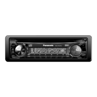
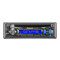
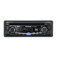
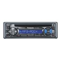
CQ-C1120AN / CQ-C1120GN / CQ-C1110AN / CQ-C1110GN / CQ-C1100VN

 Loading...

