Do you have a question about the Panasonic CQ-C1001W1 and is the answer not in the manual?
Covers basic specifications like power supply, tone controls, and output.
Details frequency range and usable sensitivity for FM reception.
Lists frequency range and usable sensitivity for AM reception.
Specifies sampling frequency, pick-up type, and frequency response.
Notes regarding alignment of the AM/FM package block.
Notes on servo alignment points for the CD deck.
Shows the block diagram of the main unit's integrated circuits.
Detailed wiring diagram for the main circuit board (top view).
Detailed wiring diagram for the main circuit board (bottom view).
Wiring diagram for the display unit (top and bottom views).
Wiring diagram for the CD interface board (bottom view).
Schematic diagram for the main block circuits.
Continuation of the main block schematic diagram.
Schematic diagram for the display block.
Schematic diagram for the CD servo block.
Schematic diagram of the main block, left side.
Schematic diagram of the main block, right side.
| Brand | Panasonic |
|---|---|
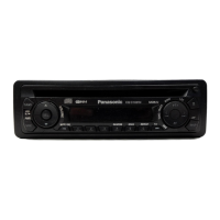
| Model | CQ-C1001W1 |
| Category | Car Receiver |
| Language | English |