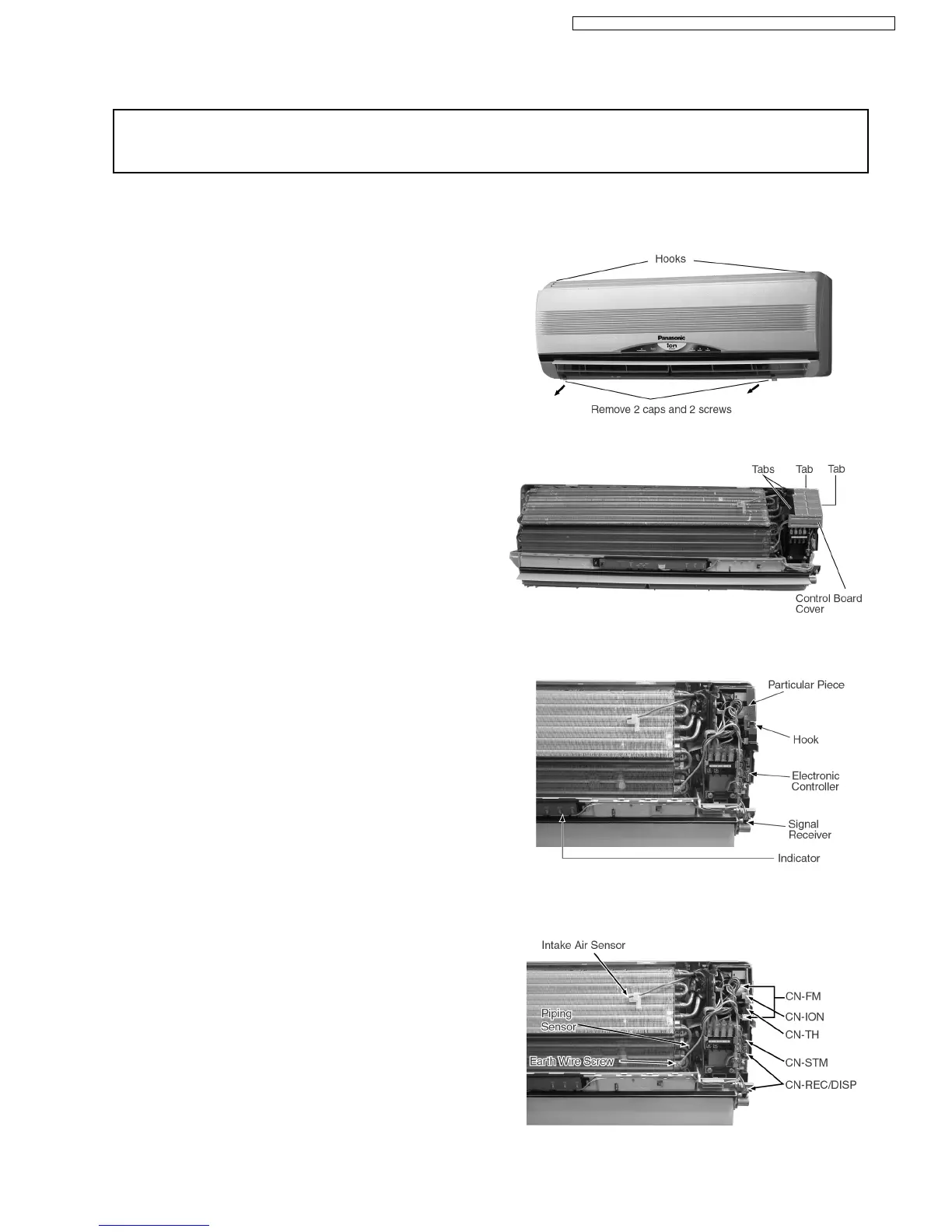
1. The Electronic Controller, a Signal Receiver and an
Indicator (Fig. 3) can be seen by the below steps:
•
Remove the 2 caps and 2 screws at the bottom of the
Front Grille. (Fig. 1)
•
Remove the Front Grille by releasing the 2 hooks at the
top of the Front Grille. (Fig. 1)
•
Remove the Control Board Cover by releasing the 2
tabs at left, 1 tab on top and 1 tab at right side of the
Control Board Cover. (Fig. 2)
2. To remove the Electronic Controller:
•
Release the Particular Piece. (Fig. 3)
•
Release the hook that hold the Electronic Controller.
(Fig. 3)
•
Remove the Control Board by:-
−
Releasing CN-REC/DISP connectors. (Fig. 4)
−
Releasing CN-FM connectors. (Fig. 4)
−
Releasing CN-ION connector. (Fig. 4)
−
Releasing CN-STM connector. (Fig. 4)
−
Removing the Earth Wire screw. (Fig. 4)
−
Releasing the Intake Air Sensor. (Fig. 4)
−
Releasing the Piping Sensor. (Fig. 4)
Fig. 1
Fig. 2
Fig. 3
Fig. 4
12 Servicing Information
Caution:
•
Pb free solder has a higher melting point than standard solder; Typically the melting point is 50 - 70°F(30-40°C) higher. Please use
a high temperature soldering iron. In case of the soldering iron with temperature control, please set it to 700 ± 20°F (370 ± 10°C).
•
Pb free solder will tend to splash when heated too high (about 1100° F/600°C).
12.1. Indoor Electronic Controllers Removal Procedures
12.2. Indoor Fan Motor and Cross Flow Fan Removal Procedures
67
CS-A7CKP CU-A7CKP5 / CS-A9CKP CU-A9CKP5 / CS-A12CKP CU-A12CKP5