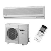
Do you have a question about the Panasonic CS-A95KE and is the answer not in the manual?
Highlights efficiency, design, comfort, filters, quality, service and operation improvements.
Explains operation modes, fan speed, temperature settings, timers, and airflow.
Details automatic operation, indicator lamps, sleep mode, fan speed, and airflow controls.
Covers compressor protection, deice, overload, fan motor, and 4-way valve controls.
Lists cooling/heating capacity, moisture removal, power source, airflow, volume, noise, electrical data, and piping.
Provides front, side, and back views with measurements for the indoor unit.
Shows installation space and unit dimensions for different models.
Presents the electrical schematic and component color codes.
Lists resistance measurements for fan motors and compressor windings.
Explains controls like time delay, starting current, anti-freezing, and compressor protection.
Details soft dry operation, fan speed, and protection controls.
Covers time delay, overload, compressor reverse rotation, and 4-way valve controls.
Describes how the unit automatically selects operation modes and sets temperatures.
Includes Sleep Mode, Random Auto Restart, Delay ON Timer, and Remote Control Signal Sound.
Explains auto and manual fan speed adjustments for different modes.
Details vertical and horizontal airflow adjustments for different modes.
Describes power saving by adjusting temperature and fan speed.
Explains rapid temperature adjustment with increased fan speed.
General warnings and cautions for safe operation and handling.
Warnings related to proper installation procedures and grounding.
Lists prohibited actions and mandatory steps during unit operation.
Labels and identifies components of the indoor unit.
Labels and identifies components of the outdoor unit.
Shows and names included accessories like remote control and batteries.
Details the remote control layout, buttons, and display functions.
Explains how to use the remote, including inserting batteries and setting time.
Steps for connecting power, opening the panel, and inserting filters.
Specifies optimal temperature ranges for cooling and heating operations.
Guides on selecting modes like Auto, Cooling, Soft Dry, and setting temperature.
Explains heating-specific operations like defrosting and automatic airflow.
Step-by-step guide for setting ON and OFF timers for unit operation.
How to cancel timers and details on their operation timing.
Describes automatic temperature adjustment for comfortable sleep.
Explains power-saving and rapid cooling/heating modes with their effects.
Instructions for cleaning the main unit and remote control.
Detailed steps for cleaning the air filters to maintain efficiency.
Steps for removing, cleaning, and reattaching the front panel.
Guide on replacing filters, including frequency and type.
Checks to perform before use and regularly for optimal performance.
Procedures for proper storage of the unit when not in use.
Addresses common sounds and phenomena during normal unit operation.
Lists symptoms of abnormal operation and when to call a dealer.
Information on critical issues requiring immediate professional service.
Using pressure and temperature readings to diagnose system issues.
How pressure and current relate to different fault conditions.
Methods for diagnosing compressor and valve failures.
Graphs showing thermostat operation under various temperature conditions.
Tables detailing cooling and heating capacities based on temperatures.
Performance data including cooling, heating, and piping length effects.
Performance data including cooling, heating, and piping length effects.
Performance data including cooling, heating, and piping length effects.
Visual breakdown of the indoor unit parts for identification.
List of replacement parts for CS-A75KE, CS-A95KE, and CS-A125KE models.
Visual breakdown of the CU-A75KE / CU-A95KE unit parts.
List of replacement parts for CU-A75KE and CU-A95KE models.
Visual breakdown of the CU-A125KE unit parts.
List of replacement parts for the CU-A125KE model.
Lists electronic components used in the controller board.
Part one of the electronic circuit diagram detailing system connections.
Part two of the electronic circuit diagram detailing system connections.
Part three of the electronic circuit diagram detailing system connections.
Circuit diagram specific to the wireless remote control unit.
Visual layout of components on the top side of the indoor unit PCB.
Visual layout of components on the bottom side of the indoor unit PCB.
| Brand | Panasonic |
|---|---|
| Model | CS-A95KE |
| Category | Air Conditioner |
| Language | English |


 Loading...