EasyManua.ls Logo

Panasonic CS-C12GKZW User Manual

Panasonic CS-C12GKZW
64 pages
To Next Page IconTo Next Page
Page #1 background imageLoading...
Page #1 background image
© 2007 Panasonic HA Air-Conditioning (M) Sdn. Bhd.
(11969-T). All rights reserved. Unauthorized copying and
distribution is a violation of law.
Order No. MAC0704020C3
Air Conditioner
CS-C12GKZW CU-2C24CKH
CS-C14GKZW CU-2C23CKH
CS-C9GKZW
TABLE OF CONTENTS
PAGE PAGE
1 Safety Precautions----------------------------------------------- 2
2 Specifications ----------------------------------------------------- 4
2.1. CS-C12GKZW CS-C12GKZW CU-2C24CKH ----- 4
2.2. CS-C14GKZW CS-C9GKZW CU-2C23CKH ------- 6
3Features------------------------------------------------------------- 8
4 Location of Controls and Components ------------------- 9
4.1. Product Overview------------------------------------------ 9
5Dimensions--------------------------------------------------------10
5.1. Indoor Unit & Remote Control-------------------------10
5.2. Outdoor Unit -----------------------------------------------11
6 Refrigeration Cycle Diagram --------------------------------12
6.1. CS-C12GKZW CS-C12GKZW CU-2C24CKH ----12
6.2. CS-C14GKZW CS-C9GKZW CU-2C23CKH ------12
7 Block Diagram----------------------------------------------------13
7.1. CS-C12GKZW CS-C12GKZW CU-2C24CKH ----13
7.2. CS-C14GKZW CS-C9GKZW CU-2C23CKH ------14
8 Wiring Connection Diagram ---------------------------------15
8.1. CS-C12GKZW CS-C12GKZW CU-2C24CKH ----15
8.2. CS-C14GKZW CS-C9GKZW CU-2C23CKH------ 16
9 Electronic Circuit Diagram----------------------------------- 17
10 Printed Circuit Board ------------------------------------------ 18
10.1. Indoor Unit ------------------------------------------------- 18
10.2. Indicator ---------------------------------------------------- 20
10.3. Patrol-------------------------------------------------------- 20
11 Installation Instruction ---------------------------------------- 21
11.1. Select The Best Location ------------------------------ 21
11.2. Indoor Unit ------------------------------------------------- 22
11.3. Outdoor Unit----------------------------------------------- 24
12 Operation and Control ---------------------------------------- 27
12.1. Cooling Operation---------------------------------------- 27
12.2. Soft Dry Operation--------------------------------------- 28
12.3. Automatic Operation ------------------------------------ 29
12.4. Operation Control---------------------------------------- 30
12.5. Indoor Fan Speed Control ----------------------------- 33
12.6. Outdoor Fan Speed Control --------------------------- 34
12.7. Vertical Airflow Direction Control--------------------- 35

Table of Contents

Question and Answer IconNeed help?

Do you have a question about the Panasonic CS-C12GKZW and is the answer not in the manual?

Panasonic CS-C12GKZW Specifications

General IconGeneral
TypeSplit System
Cooling Capacity3.52 kW
Compressor TypeRotary
RefrigerantR32
Power Supply220-240 V, 50 Hz

Summary

Safety Precautions

Specifications

CS-C12GKZW/CU-2C24CKH Specifications

Detailed technical specifications for the CS-C12GKZW and CU-2C24CKH models.

CS-C14GKZW/CU-2C23CKH Specifications

Detailed technical specifications for the CS-C14GKZW and CU-2C23CKH models.

Features

Location of Controls and Components

Indoor Unit Overview

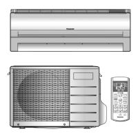
Details the location of controls and components within the indoor unit.

Outdoor Unit Overview

Details the location of controls and components within the outdoor unit.

Remote Control Overview

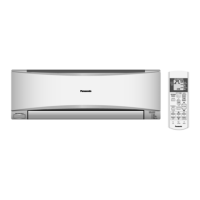
Details the layout and functions of the remote control.

Dimensions

Indoor Unit & Remote Control Dimensions

Dimensional drawings and specifications for the indoor unit and remote control.

Outdoor Unit Dimensions

Dimensional drawings and specifications for the outdoor unit.

Refrigeration Cycle Diagrams

CS-C12GKZW/CU-2C24CKH Diagram

Illustrates the refrigeration cycle for the CS-C12GKZW/CU-2C24CKH model.

CS-C14GKZW/CU-2C23CKH Diagram

Illustrates the refrigeration cycle for the CS-C14GKZW/CU-2C23CKH model.

Block Diagrams

CS-C12GKZW/CU-2C24CKH Block Diagram

Electrical block diagram for the CS-C12GKZW/CU-2C24CKH model.

CS-C14GKZW/CU-2C23CKH Block Diagram

Electrical block diagram for the CS-C14GKZW/CU-2C23CKH model.

Wiring Connection Diagrams

CS-C12GKZW/CU-2C24CKH Wiring Diagram

Detailed wiring diagram for the CS-C12GKZW/CU-2C24CKH model.

CS-C14GKZW/CU-2C23CKH Wiring Diagram

Detailed wiring diagram for the CS-C14GKZW/CU-2C23CKH model.

Electronic Circuit Diagram

Printed Circuit Board Components

Indoor Unit PCB Layout

Illustrates the layout of the indoor unit's printed circuit board.

Indicator LEDs and Patrol Module

Shows the layout of indicator LEDs and the patrol module on PCBs.

Installation Instructions

Location Selection

Guidelines for selecting the ideal installation site for optimal performance and safety.

Indoor Unit Installation Steps

Detailed steps for installing the indoor unit, including plate mounting and drilling.

Outdoor Unit Installation and Piping

Instructions for installing the outdoor unit, connecting piping, and purging the system.

Operation and Control

Core Operation Modes

Explains cooling, soft dry, and automatic operation modes and their controls.

Fan, Airflow, and Specialized Operations

Details fan speed, airflow, quiet, powerful, patrol, and e-ion operations.

Timers, Restart, and Safety Controls

Covers timer settings, auto-restart, and protective controls like freeze prevention.

Quiet Operation

Patrol Operation Details

Gas Sensor and Dirtiness Level

How the gas sensor monitors air quality and determines dirtiness levels.

e-ion Air Purifying Control

Explains the e-ion system activation based on air quality.

Fan, Airflow, and Indicator Controls

Details fan speed, airflow direction, and indicator status during patrol operation.

Timer, Power Failure, and Sound Feedback

Explains timer, power failure handling, and sound indications for patrol mode.

e-ion Operation

e-ion Operation Controls and Modes

Explains fan speed, airflow, timer, and indicator behavior during e-ion operation.

e-ion Check Mode and Error Detection

Covers e-ion check mode, power failure recovery, and error detection methods.

Servicing Modes

Auto OFF/ON Button Functions

Explains auto operation, test run, and sound control modes.

Remote Control Code Selection

Procedure for selecting and setting remote control transmission codes.

Remote Control Buttons

SET and Clock Button Functions

Details the SET button for code/sensitivity and CLOCK button for time format.

Reset and Timer Button Functions

Explains the RESET button and timer adjustments for LED intensity and display units.

Troubleshooting Guide

Refrigeration Cycle Diagnosis

Guide for diagnosing malfunctions based on refrigeration cycle parameters and compressor behavior.

Disassembly and Assembly

Indoor Unit Control Board Removal

Step-by-step guide to remove indoor electronic controllers and the main control board.

Indoor Fan Motor and Fan Removal

Procedures for safely removing the indoor fan motor and cross flow fan assembly.

Technical Data

Thermostat Characteristics

Graphs illustrating thermostat behavior in cooling and soft dry modes.

Model Operation Characteristics

Performance data graphs (cooling, pressure, current) for different models and conditions.

Compressor OLP Characteristics

Graphs detailing the thermal protection characteristics of compressor OLP devices.

Exploded Views and Parts Lists

Indoor Unit Components

Exploded view and parts list for the indoor unit assembly.

Outdoor Unit Components

Exploded view and parts list for the outdoor unit assembly.

Related product manuals