Do you have a question about the Panasonic CS-C12MKF and is the answer not in the manual?
General safety guidelines and precautions for servicing the air conditioner unit.
Explanation of warning and caution symbols used throughout the manual.
Detailed technical specifications for indoor and outdoor units, including capacity, power, and noise levels.
Physical dimensions, piping details, heat exchanger, and material specifications for the units.
Indoor and outdoor operating temperature ranges and power supply details.
Details on the E-ion Air Purifying System with Patrol Sensor functionality.
Information on long installation piping capabilities and remote control features.
Highlights of quality improvements and operational enhancements like auto-restart and quiet mode.
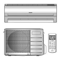
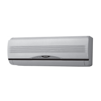
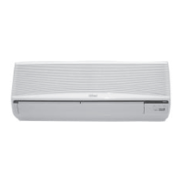
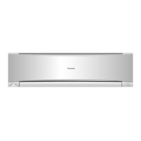
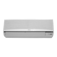
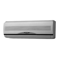
Identification and location of controls and components on the indoor unit.
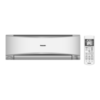
Location of outdoor unit components and overview of the remote control.
Detailed dimensions and views of the indoor unit models.
Dimensions and views for CU-C12MKF and CU-C18MKF outdoor units.
Dimensions and views for the CU-C24MKF outdoor unit.
Dimensions and views for the CU-C28MKF outdoor unit.
Block diagram for the CS-C12MKF / CU-C12MKF model.
Block diagrams for CS-C18MKF/CU-C18MKF and CS-C24MKF/CU-C24MKF models.
Block diagram for the CS-C28MKF / CU-C28MKF model.
Wiring connection diagram for CS-C12MKF / CU-C12MKF models.
Wiring connection diagram for CS-C18MKF / CU-C18MKF models.
Wiring connection diagram for CS-C24MKF / CU-C24MKF models.
Wiring connection diagram for CS-C28MKF / CU-C28MKF models.
Electronic circuit diagram for CS-C12MKF / CU-C12MKF models.
Electronic circuit diagram for CS-C18MKF / CU-C18MKF models.
Electronic circuit diagram for CS-C24MKF / CU-C24MKF models.
Electronic circuit diagram for CS-C28MKF / CU-C28MKF models.
Layout of the main printed circuit board for CS-C12MKF indoor unit.
Layout of the main printed circuit board for CS-C18/C24/C28MKF indoor units.
Layouts for indicator, receiver, high voltage, and comparator PCBs.
Layout of the human activity sensor printed circuit board.
Guidelines for choosing the optimal location for indoor and outdoor units.
Steps for mounting the indoor unit, drilling holes, and connecting cables.
Procedures for installing the outdoor unit and connecting refrigerant piping.
Instructions for evacuation and air purging of the refrigerant system.
Guidance on selecting the best location for the C28MKF unit.
Detailed steps for fixing the indoor unit mounting plate and drilling wall holes.
Steps for installing the outdoor unit and connecting refrigerant piping.
Procedures for evacuation and air purging of the refrigerant cycle.
Instructions for connecting the indoor unit power and connection cables.
Requirements for stripping wires and connecting them properly.
Procedure for cutting and flaring copper piping for connections.
Steps for installing the outdoor unit on a firm base.
Procedure for connecting refrigerant piping to the outdoor unit.
Steps for evacuating the equipment using a vacuum pump.
Procedure for purging air from the refrigerant piping.
Instructions for connecting power supply and inter-unit cables to the outdoor unit.
Guidance on insulating outdoor unit piping.
Details on setting and operating the cooling mode.
Information on the soft dry operation for dehumidification and gentle cooling.
Explanation of automatic operation based on intake air temperature.
Methods for controlling indoor fan speed, including charts and automatic control.
Control of vertical louvers in auto and manual modes.
Control of horizontal louvers in auto and manual modes.
Details on the powerful operation mode for rapid temperature adjustment.
Explanation of the quiet operation mode for reduced noise levels.
Information on setting ON and OFF timers, and auto-restart functions.
Description of the Patrol operation for monitoring air dirtiness and freshness.
Explanation of E-ion operation, fan control, and airflow direction.
Procedure for checking E-ion sensor serviceability and abnormality.
Information on E-ion indicator blinking and error detection methods.
Overview of AUTO COMFORT and ECO NAVI operations for energy saving.
Details on signal detection, information logging, and activity level judgment.
How installation position affects horizontal airflow direction judgment.
Procedures for enabling and disabling ECO NAVI and AUTO COMF Demo Modes.
Controls for compressor restart, time save, forced operation, and starting current.
Controls for freeze prevention and compressor reverse rotation protection.
Mechanism to prevent dew formation at the indoor unit discharge area.
Explanation of servicing modes accessed via the Auto OFF/ON button.
Operations for SET, RESET, TIMER UP/DOWN buttons on the remote control.
Diagnosing problems related to the refrigeration cycle via temperature and pressure.
Methods for diagnosing compressor malfunctions like insufficient compression or locking.
Step-by-step guide to disassembling the CS-C12MKF indoor unit components.
Disassembly steps for CS-C18MKF and CS-C24MKF indoor unit components.
Disassembly steps for the CS-C28MKF indoor unit components.
Graphs showing operation characteristics versus outdoor temperature for CS-C12MKF.
Graphs showing characteristics versus piping length for CS-C12MKF.
Graphs showing operation characteristics versus outdoor temperature for CS-C18MKF.
Graphs showing characteristics versus piping length for CS-C18MKF.
Cooling performance data tables for CS-C12MKF / CU-C12MKF.
Cooling performance data tables for CS-C18MKF / CU-C18MKF.
Cooling performance data tables for CS-C24MKF / CU-C24MKF.
Cooling performance data tables for CS-C28MKF / CU-C28MKF.
Exploded view diagram and parts list for CS-C12MKF indoor unit.
Detailed parts list for CS-C12MKF indoor unit, including part numbers.
Exploded view diagrams for CS-C18/C24/C28MKF indoor units.
Parts list for CS-C18/C24/C28MKF indoor units.
Exploded view diagram for the CU-C12MKF outdoor unit.
Parts list for the CU-C12MKF outdoor unit, including part numbers.
Exploded view diagram for the CU-C18MKF outdoor unit.
Parts list for the CU-C18MKF outdoor unit, including part numbers.
Exploded view diagram for the CU-C24MKF outdoor unit.
Exploded view diagram for the CU-C28MKF outdoor unit.
Parts lists for CU-C24MKF and CU-C28MKF outdoor units.
| Type | Split System |
|---|---|
| Power Supply | 220-240V, 50Hz |
| Cooling Capacity | 3.5 kW |
| Heating Capacity | 4.0 kW |
| Power Consumption (Cooling) | 1080 W |
| Power Consumption (Heating) | 1.05 kW |