Do you have a question about the Panasonic CS-E18CKE and is the answer not in the manual?
| Brand | Panasonic |
|---|---|
| Model | CS-E18CKE |
| Category | Air Conditioner |
| Language | English |
Explains remote control functions, modes, timers, and settings like temperature.
Specifies cooling capacity values in kW, kcal/h, and BTU/h for different models.
Specifies heating capacity values in kW, kcal/h, and BTU/h for different models.
Provides input power, running current, EER, COP, and starting current.
Diagrams showing indoor unit dimensions and relative positions for installation.
Diagrams showing outdoor unit dimensions and space requirements for installation.
Detailed wiring diagram with component labels, wire colors, and remarks.
Overview of microcomputer control, temperature shifting, and compressor frequency.
Control of compressor frequency based on temperature and operation mode.
Operation mode chart and temperature adjustments.
Outline of the indoor fan control logic for various operations.
Conditions for maximum capacity fan speed and fan motor control.
How vertical airflow direction is controlled automatically and manually.
Purpose, conditions, and control contents for quiet cooling operation.
Purpose, conditions, and control contents for quiet heating operation.
How powerful mode achieves quick temperature setting by adjusting internal temperature.
Details fan motor speeds (rpm) for different modes and models.
Explanation of airflow types (vertical/horizontal) and control methods.
Function and operation of the delay ON timer for early startup.
Explanation of LED indicators and their meanings.
Methods for detecting and handling ionizer problems.
Function of the delay OFF timer for stopping operation at a set time.
Decision process for automatic operation based on various temperatures.
General protection controls applicable to all operating modes.
Controls for CT disconnection, low frequency, and minimum frequency.
Protection controls specific to cooling and soft dry operation modes.
Anti-freezing and anti-dew formation controls for cooling/soft dry modes.
Protection controls specific to heating operation mode.
Explanation of deice operation and conditions triggering it.
Auto clean deice time chart and notes on deice sequence.
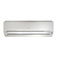
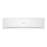
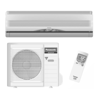
General overview of the outdoor unit, indoor unit, and remote control.
How to control airflow direction and fan speed using the remote.
Instructions for setting and using the unit's timers.
How to activate and deactivate the quiet operation mode.
Introduction to the remote control and its basic functions.
How to activate the powerful mode for faster cooling or heating.
Instructions for starting and operating the unit in various modes.
Details on how to operate the unit in automatic mode.
Instructions for operating the unit in heating mode.
Instructions for operating the unit in cooling mode.
Instructions for operating the unit in dry (dehumidifying) mode.
Instructions for operating the unit in fan-only mode.
Instructions for cleaning or replacing air filters.
General guide for troubleshooting common issues.
Troubleshooting sudden stops in cooling, dry, and heating modes.
Troubleshooting issues with the remote control and display.
Troubleshooting steps when the unit does not operate.
Troubleshooting steps for excessive operational noise.
Troubleshooting steps for low cooling or heating efficiency.
Immediate actions required in case of emergency, like smell of burning.
Safety precautions to follow during unit operation.
Safety precautions to follow during installation.
Safety precautions for electrical connections.
Action to take if a defect or suspicion of defect is present.
Instructions for cleaning the unit's components.
Explanation of the automatic operation mode.
Introduction to R410A refrigerant and its properties.
Using electronic scales for accurate refrigerant charging.
Details on R410A refrigerant, its environmental impact, and characteristics.
Chemical and physical characteristics of R410A refrigerants.
Description of specific R410A tools and their functions.
Crucial safety measures for handling R410A refrigerant piping.
List of essential tools required for R410A refrigerant piping work.
Detailed list of necessary tools for R410A installation and servicing.
Tools required for installation, transfer, and replacement tasks.
Tools required specifically for servicing operations.
Recommended piping materials and standards for R410A systems.
Precautions for flare connections, including torque specifications.
Procedures and precautions for processing and connecting refrigerant pipes.
Steps and important precautions for performing pipe flaring.
Steps and precautions for making flare connections.
Proper flaring technique using appropriate tools and gauges.
Procedure for inspecting gas leaks using a vacuum pump.
Procedures for transferring the unit using new refrigerant piping.
Steps for setting up refrigerant cylinder, scale, and charging.
Techniques and precautions for brazing refrigerant pipes.
Setting up the refrigerant cylinder and connecting to the scale.
Method to prevent pipe oxidation during brazing using nitrogen gas.
General cautions and specific considerations for brazing.
Operating the vacuum pump and checking for vacuum.
Considerations when replacing AC units using existing refrigerant piping.
Purging air from the charging hose and system.
Opening/closing valves and performing a gas leak inspection.
Charging the system with liquid refrigerant.
Warnings about mixing R410A and R22 refrigerants.
Procedure for recharging refrigerant during servicing.
Completing the refrigerant charging process.
Tips for servicing, including drier replacement and vacuuming.
Important notes regarding vacuum pump and charging hose usage.
List of tools necessary for performing installation.
General safety warnings and symbols for installation.
Importance of proper earthing to prevent electrical shock.
Emphasis on carefully reading all safety precautions before proceeding.
Warning against installing near flammable gas leaks.
Requirement for licensed electrician and correct power rating.
Importance of proper drainage piping to prevent water damage.
Explanation of safety indications and consequences of ignoring instructions.
Guidelines for choosing a suitable and accessible installation location.
Methods for connecting the power supply to the unit.
Connecting the unit via a circuit breaker.
Warning against releasing refrigerant during installation or servicing.
Warning about consequences of user-installed defects.
Emphasizes strict adherence to installation instructions.
Importance of using specified parts for installation.
Requirement for a secure and strong installation location.
Safety and requirements for electrical work.
Cable connection safety and requirements.
Proper wire routing and control board cover fixing.
Preventing air and substances entry during piping connections.
Reiteration of preventing air and substances entry into the refrigeration cycle.
Specific warnings regarding R410A piping and copper pipe usage.
Warning against using R22 parts with R410A systems.
Requirement for copper pipe thickness in R410A systems.
Limit for residual oil in pipes.
Warnings about power cord modification and sharing outlets.
Diagram showing installation layout, components, and clearances.
Procedure for evacuating air from the indoor unit and piping.
Emphasizing procedure to prevent refrigerant gas leaks.
Cautions regarding gauge needle movement and leak detection.
Diagnosing malfunctions by analyzing refrigeration cycle parameters.
Table of error codes, their causes, and primary locations for verification.
General troubleshooting guide for diagnosing unit malfunctions.
How to use the unit's self-diagnosis feature to identify errors.
Safety warnings for handling the outdoor electronic controller.
Performance data including cooling/heating characteristics and piping length effects.
Capacity data (TC, SHC, IP) based on indoor/outdoor temperatures.
Exploded view diagram of the indoor unit with numbered parts.
List of replaceable parts for CS-E18CKE and CS-E21CKE models.
Exploded view diagram of the outdoor unit with numbered parts.
List of replaceable parts for CU-E18CKR and CU-E21CKR models.
Schematic diagram of the main electronic control unit (part 1/3).
Circuit diagram showing receiver, sensors, and control logic.
Circuit diagram illustrating the high voltage and converter unit.
Detailed circuit diagram of the power supply and control sections.
Circuit diagram showing sensor inputs and power supply components.
Circuit diagram detailing the MICON and related control circuits.
Circuit diagram showing motor drivers and protection circuits.
Final part of the circuit diagram showing sensors and output drivers.
Print pattern layout of the indoor unit's main printed circuit board.
Print pattern layout of the outdoor unit's main printed circuit board.