Do you have a question about the Panasonic CS-E18EKK and is the answer not in the manual?
Specifications for CS-E18EKK CU-E18EKK model, including performance and electrical data.
Specifications for CS-E21EKK CU-E21EKK model, including performance and electrical data.
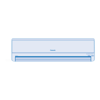
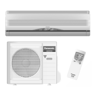
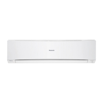
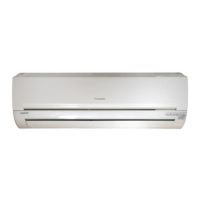
Details the location of controls and components on the indoor unit.
Details the location of controls and components on the outdoor unit.
Details the location of controls and components on the remote control.
Provides dimensional information for the indoor unit and remote control.
Provides dimensional information for the outdoor unit.
Wiring diagram for CS-E18EKK and CS-E21EKK indoor units.
Wiring diagram for CU-E18EKK and CU-E21EKK outdoor units.
Diagram of the main printed circuit board for the indoor unit.
Diagram of the main printed circuit board for the outdoor unit.
Guidelines for selecting optimal indoor and outdoor unit installation locations.
Detailed procedures for installing the indoor unit.
Detailed instructions for handling embedded piping during indoor unit installation.
Procedure for connecting the electrical wiring for the indoor unit.
Instructions for installing the Super Alleru-buster filter.
Procedure for removing and reinstalling the front grille for servicing.
Guidelines for selecting the best location and installing the outdoor unit.
Steps for connecting the refrigerant piping to the indoor and outdoor units.
Procedure for evacuating air from the refrigeration system.
Procedure for connecting the electrical wiring for the outdoor unit.
Instructions for insulating pipes to prevent condensation.
Procedure to verify proper drainage functionality of the indoor unit.
Steps to evaluate the air conditioner's performance after installation.
Overview of the inverter control and basic operational functions.
Explanation of how internal setting temperature is determined and updated.
Details on vertical and horizontal airflow control methods.
How to control vertical airflow direction using the remote control.
How to control horizontal airflow direction using the remote control.
Purpose and control conditions for quiet operation mode.
Specifics of quiet operation during Soft Dry mode for indoor fan and compressor.
Purpose and control conditions for quiet operation in heating mode.
How powerful mode operation achieves faster temperature setting.
How the ON timer allows earlier operation start for comfort.
How the OFF timer allows setting a specific stop time.
How the unit restarts automatically after a power interruption.
Overview of various protection mechanisms for the air conditioner.
Ensures compressor does not start for three minutes after stopping.
The compressor runs for 30 seconds after starting, with exceptions.
Mechanism to decrease or stop compressor based on running current.
Protection against abnormal current and overheating of IPM.
Protects compressor from overheating via discharge pipe temperature monitoring.
Prevents operation issues due to high pressure in outdoor unit.
Protects compressor from abnormalities in the refrigeration cycle.
Detects abnormalities in the four-way valve during cooling/heating switching.
Prevents freezing by adjusting operation based on heat exchanger temperature.
Limits maximum power based on outdoor air temperature.
Limits maximum power based on indoor intake air temperature during heating.
Details operations performed by pressing the 'AUTO' switch for servicing.
Explanation of the indicator panel lights and their meanings.
Diagnosing malfunctions related to the refrigeration cycle system.
Correlations between air conditioner conditions, pressure, and electric current.
How to use the self-diagnosis function to identify breakdowns.
Table listing error codes, their meanings, and primary verification locations.
Procedure for disassembling the indoor unit's electronic controller and control board.
Procedure for disassembling the indoor unit's cross flow fan and fan motor.
Procedure for disassembling the outdoor unit's propeller fan and fan motor.
Cooling characteristics of CS-E18EKK CU-E18EKK at different outdoor air temperatures.
Current characteristics of CS-E18EKK CU-E18EKK at different outdoor air temperatures.
Heating characteristics of CS-E18EKK CU-E18EKK at different outdoor air temperatures.
Cooling performance characteristics based on piping length for CS-E18EKK.
Heating performance characteristics based on piping length for CS-E18EKK.
Cooling characteristics of CS-E21EKK CU-E21EKK at different outdoor air temperatures.
Current characteristics of CS-E21EKK CU-E21EKK at different outdoor air temperatures.
Heating characteristics of CS-E21EKK CU-E21EKK at different outdoor air temperatures.
Cooling performance characteristics based on piping length for CS-E21EKK.
Heating performance characteristics based on piping length for CS-E21EKK.
Chart detailing sensible cooling capacity under various conditions.
Exploded view diagram for CS-E18EKK CS-E21EKK models.
Replacement parts list for CS-E18EKK CS-E21EKK models.
Exploded view diagram for CU-E18EKK CU-E21EKK models.
Replacement parts list for CU-E18EKK CU-E21EKK models.
| Brand | Panasonic |
|---|---|
| Model | CS-E18EKK |
| Category | Air Conditioner |
| Language | English |