EasyManua.ls Logo

Panasonic CS-E7GKDW CU-E7GKD User Manual

Panasonic CS-E7GKDW CU-E7GKD
71 pages
To Next Page IconTo Next Page
Page #1 background imageLoading...
Page #1 background image
© 2006 Panasonic HA Air-Conditioning (M) Sdn. Bhd.
(11969-T). All rights reserved. Unauthorized copying
and distribution is a violation of law.
Order No. MAC0612062C8
Air Conditioner
CS-E7GKDW CU-E7GKD
CS-E9GKDW CU-E9GKD
CS-E12GKDW CU-E12GKD
TABLE OF CONTENTS
PAGE PAGE
1 Safety Precaution ------------------------------------------------ 2
2 Specifications ----------------------------------------------------- 4
2.1. CS-E7GKDW CU-E7GKD------------------------------ 4
2.2. CS-E9GKDW CU-E9GKD------------------------------ 6
2.3. CS-E12GKDW CU-E12GKD--------------------------- 8
3Features------------------------------------------------------------10
4 Location of Controls and Components ------------------11
4.1. Product Overview-----------------------------------------11
5Dimensions--------------------------------------------------------12
5.1. Indoor Unit--------------------------------------------------12
5.2. Outdoor Unit -----------------------------------------------13
6 Refrigeration Cycle Diagram --------------------------------14
7 Block Diagram----------------------------------------------------15
8 Wiring Connection Diagram --------------------------------16
8.1. Indoor Unit--------------------------------------------------16
8.2. Outdoor Unit -----------------------------------------------17
9 Electronic Circuit Diagram -----------------------------------18
9.1. Indoor Unit ------------------------------------------------- 18
9.2. Outdoor Unit----------------------------------------------- 19
10 Printed Circuit Board ------------------------------------------ 20
10.1. Indoor Unit ------------------------------------------------- 20
10.2. Outdoor Unit----------------------------------------------- 22
11 Installation Instruction ---------------------------------------- 23
11.1. Select The Best Location ------------------------------ 23
11.2. Indoor/Outdoor Unit Installation Diagram ---------- 23
11.3. Indoor Unit ------------------------------------------------- 24
11.4. Outdoor Unit----------------------------------------------- 27
12 Operation and Control ---------------------------------------- 30
12.1. Basic Function -------------------------------------------- 30
12.2. Protection Control---------------------------------------- 40
13 Servicing Mode-------------------------------------------------- 44
13.1. Auto OFF/ON Button------------------------------------ 44
13.2. Select Remote Control Transmission Code------- 44
13.3. Remote Control Button --------------------------------- 45
Question and Answer IconNeed help?

Do you have a question about the Panasonic CS-E7GKDW CU-E7GKD and is the answer not in the manual?

Panasonic CS-E7GKDW CU-E7GKD Specifications

General IconGeneral
BrandPanasonic
ModelCS-E7GKDW CU-E7GKD
CategoryAir Conditioner
LanguageEnglish

Summary

Safety Precaution

Specifications

CS-E7GKDW CU-E7GKD Specifications

Technical specifications for the CS-E7GKDW CU-E7GKD model.

CS-E9GKDW CU-E9GKD Specifications

Technical specifications for the CS-E9GKDW CU-E9GKD model.

CS-E12GKDW CU-E12GKD Specifications

Technical specifications for the CS-E12GKDW CU-E12GKD model.

Features

Controls and Components

Product Overview

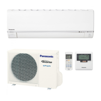
Overview of indoor unit, outdoor unit, and remote control components.

Dimensions

Indoor Unit Dimensions

Detailed dimensions for the indoor unit.

Outdoor Unit Dimensions

Detailed dimensions for the outdoor unit.

Refrigeration Cycle Diagram

Block Diagram

Wiring Connection Diagram

Indoor Unit Wiring

Wiring diagram for the indoor unit.

Outdoor Unit Wiring

Wiring diagram for the outdoor unit.

Electronic Circuit Diagram

Indoor Unit Circuits

Electronic circuit diagram for the indoor unit.

Outdoor Unit Circuits

Electronic circuit diagram for the outdoor unit.

Printed Circuit Board Layouts

Indoor Unit Main PCB

Layout of the main printed circuit board for the indoor unit.

Indoor Unit Power PCB & Indicators

Layout of power PCB, indicator panel, and patrol components.

Outdoor Unit Main PCB

Printed circuit board layout for the outdoor unit.

Installation Instructions

Location Selection

Guidelines for choosing the optimal installation location.

Installation Diagram

Diagram showing the installation layout of indoor and outdoor units.

Indoor Unit Installation

Installation Plate Fixing

Instructions for fixing the installation plate.

Drilling for Piping

Process for drilling and installing piping sleeve.

Unit Mounting

Step-by-step guide for indoor unit installation.

Outdoor Unit Installation

Mounting and Piping Connection

Procedures for mounting the outdoor unit and connecting piping.

Equipment Evacuation

Steps for evacuating air from the system.

Outdoor Unit Cable Connection

Instructions for connecting outdoor unit cables.

Operation and Control

Basic Functions and Temperature Control

Overview of basic functions and temperature control logic.

Heating and Automatic Operation

Details on heating mode and automatic operation logic.

Indoor Fan Motor Operation

Details on indoor fan motor operation and speed control.

Outdoor Fan Motor Operation

Operation of the outdoor fan motor.

Airflow Direction Control

Control of vertical and horizontal airflow direction.

Horizontal Airflow and Quiet Operation

Manual horizontal airflow and quiet operation modes.

Powerful Mode and Timer Controls

Powerful mode operation and ON/OFF timer functions.

Indicators, Patrol & e-ion Operation

LED indicators, air quality monitoring, and e-ion purification system.

e-ion Operation Details

Further details on e-ion operation control and indicators.

Protection Controls

General and Compressor Protection

Protection mechanisms for general operation, IPM, and compressor.

Low Pressure & Tank Temp. Protection

Protection for low pressure and compressor tank temperature.

Frequency and Cooling Protection

Protection against low frequency and cooling overload.

Freeze, Heating & Overload Protection

Protection for freeze prevention, heating, and overload conditions.

Servicing Modes

Button Functions and Code Selection

Using servicing buttons and selecting remote control codes.

Remote Control Button Operations

Explains functions of various remote control buttons.

Troubleshooting Guide

Refrigeration Cycle Diagnosis

Diagnosing issues via refrigeration cycle parameters.

Breakdown Self Diagnosis

Using the self-diagnosis feature to identify faults.

Error Codes Table

Table listing error codes and their meanings.

Disassembly and Assembly

Indoor Unit Component Removal

Steps to remove indoor unit components like grille, controllers, and fan.

Main & Power Controller Removal

Steps for removing main and power electronic controllers.

Grille, Board & Fan Motor Removal

Steps for removing discharge grille, control board, and fan motor.

Outdoor Unit Controller Removal

Technical Data

Operation Characteristics

Performance data for CS-E7GKDW, CS-E9GKDW, and CS-E12GKDW models.

E9GKDW Operation Characteristics

Performance characteristics for model E9GKDW.

E12GKDW Operation Characteristics

Performance characteristics for model E12GKDW.

Sensible Capacity Charts

Exploded View and Parts List

Indoor Unit Parts

Exploded view and parts list for the indoor unit.

Outdoor Unit Parts

Exploded view and parts list for the outdoor unit.

Related product manuals