Do you have a question about the Panasonic CS-E7NKEW and is the answer not in the manual?
Details inverter technology benefits: wider power range, energy saving, quick cooling/heating.
Focuses on non-ozone depletion substances refrigerant (R410A).
Specifies maximum allowable piping lengths for single split connections.
Mentions ease of use for the remote control functionality.
Lists improvements like auto restart, gas leakage protection.
Covers quiet mode, powerful mode, and timer settings.
Highlights breakdown self-diagnosis function.
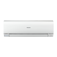
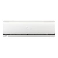
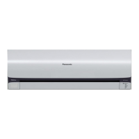
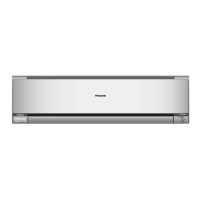
Illustrates the layout of controls and sensors on the indoor unit.
Shows the air intake and outlet sides of the outdoor unit.
Details the LCD display and buttons of the remote control.
Includes diagrams and dimensions for various indoor unit models.
Shows installation diagrams and dimensions for outdoor units.
Shows the refrigeration cycle for specific single split models.
Diagram for a specific set of multi-split compatible outdoor units.
Refrigeration cycle diagrams for CU-E18NKE and CU-E21NKE models.
Block diagrams for specific indoor/outdoor unit combinations.
Block diagrams illustrating electrical systems for CU-E12NKE/E15NKE.
Block diagrams for specific multi-split compatible models.
Block diagrams for the CU-E18NKE and CU-E21NKE models.
Wiring diagram for the indoor unit's electronic controller and motors.
Wiring diagram for the outdoor unit's electronic controller and components.
Circuit diagram for the indoor unit's main PCB and related components.
Circuit diagrams for the outdoor unit's electronic controller and sensors.
Layouts for main, indicator, power supply, comparator, and sensor PCBs.
Layouts for outdoor unit controller, sensor, and power PCBs.
Guidelines for choosing optimal indoor and outdoor installation spots.
Instructions for fixing the installation plate and drilling holes.
Details on installing the outdoor unit, connecting piping, and evacuation.
Details on how the microcomputer manages operation for comfort and efficiency.
Defines automatic mode based on temperature, mode, and air conditions.
Explains manual and auto fan speed control based on settings and conditions.
Covers vertical and horizontal airflow direction control via remote.
Details on activating and controlling quiet operation for cooling and heating.
Describes powerful mode activation and setting ON/OFF timers.
Describes AUTO COMFORT and ECO NAVI modes for comfort and energy saving.
Thermostat control specifics for cooling, soft dry, and heating in multi-split systems.
Details restart control, running current limits, and IPM protection.
Covers outdoor air temp, cooling overload, and freeze prevention.
Details intake air temp, outdoor air temp, and overload protection.
Describes functions like Auto Operation and Test Run using the button.
Details functions of SET, RESET, and TIMER buttons on the remote.
Troubleshooting based on pressure, temperature, and electric current.
Procedure for diagnosing malfunctions using error codes.
Lists error codes, their causes, and check locations.
Step-by-step guide for removing internal parts of the indoor unit.
Instructions for removing the electronic controller from the outdoor unit.
Performance data graphs for various models across different conditions.
Tables showing sensible capacity based on indoor/outdoor conditions.
Exploded view and part list for indoor unit components.
Exploded view and part list for outdoor unit components.
| Indoor unit type | Wall-mountable |
|---|---|
| Indoor units quantity | 1 |
| Indoor unit dimensions (WxDxH) | 870 x 214 x 290 mm |
| Timer | Yes |
| Built-in display | No |
| Cooling capacity (max) | - BTU/h |
| Air conditioner functions | cooling, heating |
| Cooling capacity in watts (max) | 2050 W |
| Heating capacity in watts (max) | 2800 W |
| Cooling energy efficiency (EER, W/W) | 4.36 |
| Heating energy efficiency (COP, W/W) | 4.41 |
| Outdoor units quantity | 0 |
| Noise level (low speed) | 20 dB |
| Noise level (high speed) | 37 dB |
| Noise level (medium speed) | 24 dB |
| Power requirements | AC 230 V |