1 Features 2
2 Functions
3
2.1. Remote Control
3
2.2. Indoor Unit
4
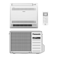
2.3. Outdoor Unit
6
3 Product Specifications
7
3.1. CS-E9DKDW CU-E9DKD
7
3.2. CS-E12DKDW CU-E12DKD
9
4 Dimensions
11
4.1. Indoor Unit & Remote Control
11
4.2. Outdoor Unit
12
5 Refrigeration Cycle Diagram
13
6 Block Diagram
14
7 Wiring Diagram
15
8 Operation Details
16
8.1. Basic Function
16
© 2004 Panasonic HA Air-Conditioning (M) Sdn Bhd
(11969-T). All rights reserved. Unauthorized copying
and distribution is a violation of law.
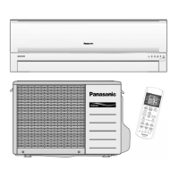
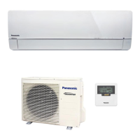
CS-E9DKDW CU-E9DKD
CS-E12DKDW CU-E12DKD
8.2. Protection Control Features 35
9 Operating Instructions
44
10 Installation Instructions
50
10.1. Safety Precautions
50
10.2. Indoor Unit
53
10.3. Outdoor Unit
57
11 Installation And Servicing Air Conditioner Using R410A
61
11.1. Outline
61
11.2. Tools For Installing/Servicing Refrigerant Piping
62
11.3. Refrigerant Piping Work
66
11.4. Installation, Transferring, Servicing
68
12 Servicing Information
72
12.1. Troubleshooting
72
12.2. Breakdown Self Diagnosis Function
74
12.3. Remote Control
76
Air Conditioner
CONTENTS
Page Page
Order No: MAC0412071C2